Novel high-Q-value capacitor

A capacitor, a new type of technology, is applied in the field of capacitors to achieve the effects of high power factor, easy processing and low cost

Pending Publication Date: 2019-05-21
FOSHAN CITY XINYUAN ELECTRONICS CO LTD
View PDF0 Cites 1 Cited by
  • Summary
  • Abstract
  • Description
  • Claims
  • Application Information

AI Technical Summary

Problems solved by technology

[0003] However, due to the difficulties in the advancement of several major industries in the technical field, capacitors with low loss angle and high power factor Q value are a difficult point that everyone has been paying attention to but difficult to solve. If it can be solved well or to a large extent If the power factor Q value can be increased, it will be favored by the mobile phone wireless charging adapter market. Therefore, the present invention proposes a new high-Q value capacitor to solve the above problems

Method used


Image

  • Novel high-Q-value capacitor
  • Novel high-Q-value capacitor
  • Novel high-Q-value capacitor

Examples


Embodiment 1

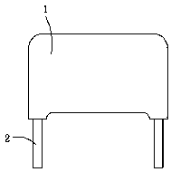
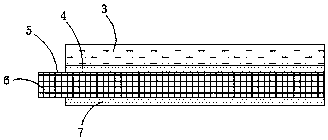
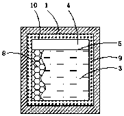
[0026] Such as Figure 1-4 As shown, a novel high-Q capacitor includes a capacitor core 10, a capacitor shell 1 and a tinned copper wire 2. The capacitor core 10 is provided with an insulating layer polypropylene film 6, and both sides of the polypropylene film 6 are By adding a small amount of shielding oil to make the first shielding layer 4 and the second shielding layer 7, the tops of the first shielding layer 4 and the second shielding layer 7 are provided with honeycomb grooves 8, and one side of the polypropylene film 6 is located in the honeycomb shape. The outer side of the groove 8 is coated with a layer of aluminum foil 3 by vacuum evaporation, and one side of the polypropylene film 6 is located on the side of the aluminum foil 3, and a margin 5 is provided; the inner side of the capacitor case 1 is bonded with epoxy glue 9. Capacitor core 10, and epoxy resin glue 9 is evenly filled between the capacitor shell 1 and the capacitor core 10, and one side of the capacit...

Embodiment 2

[0030] A vacuum evaporation processing technology for a novel high-Q capacitor, comprising the following steps: a: Polypropylene film pretreatment: first soak the polypropylene film in deionized water for 0.5-1h, then take it out, lay it flat, Put it in a vacuum dryer for high temperature drying, the drying time is 20-40min, and then perform corona treatment, and open honeycomb grooves on both sides of the polypropylene film;

[0031] b: Evaporation: first place the polypropylene film in a cleaned vacuum chamber, and heat the polypropylene film under vacuum to desorb the gas attached to the surface, then discharge it out of the vacuum chamber to improve the purity of the evaporation, and then Take a small amount of special oil and evenly spread it on the honeycomb grooves on both sides of the polypropylene film, and use it as a shielding layer, then heat and melt the aluminum foil by electron beams, and evenly coat the melted aluminum foil on the polypropylene film The special...

Embodiment 3

[0035] A vacuum evaporation process for a new high-Q capacitor, comprising the following steps: a: Polypropylene film pretreatment: first soak the polypropylene film in deionized water for 0.5-1h, then take it out, lay it flat, Put it in a vacuum dryer for high temperature drying, the drying time is 20-40min, and then perform corona treatment, and open honeycomb grooves on both sides of the polypropylene film;

[0036] b: Evaporation: first place the polypropylene film in a cleaned vacuum chamber, and heat the polypropylene film under vacuum to desorb the gas attached to the surface, then discharge it out of the vacuum chamber to improve the purity of the evaporation, and then Aluminum and zinc are melted by electron beam heating, and the molten aluminum and zinc are evenly plated on the special oil surface outside the honeycomb groove on the polypropylene film, and the surface is made smooth, and the evaporation method adopts impure The method of high square resistance of alu...


PUM


Abstract

The invention provides a novel high-Q-value capacitor, and relates to the field of capacitors. The novel high-Q-value capacitor comprises a capacitor core, a capacitor shell and tinned copper wires, wherein an insulating layer polypropylene film is arranged in the capacitor core. According to the novel high-Q-value capacitor, by changing a conventional method that the polypropylene film of the capacitor adopts traditional high-oil shielding and aluminum-zinc high-square-resistance evaporation, a small amount of special oil is added as a shielding layer in the evaporation process to prevent thepollution of a frequency band, and the phenomena of high-frequency loss and Q value reduction caused by the pollution of the frequency band due to large oil amount are avoided; meanwhile, a thin layer of aluminum is evaporated to serve as an electrode, so that the self-repair effect is achieved; the higher the Q value is, the lower the loss value of the capacitor is, the higher the efficiency is,so that double designs of low-oil shielding and pure-aluminum low-square resistance in the evaporation process are adopted to ensure a characteristic that the capacitor can realize high Q value and low loss; and the novel high-Q-value capacitor is easy to machine, relatively low in cost and relatively high in power factor, and meets the urgent needs of current wireless charging.

Description

technical field [0001] The invention relates to the field of capacitors, in particular to a novel high-Q capacitor. Background technique [0002] With the increasingly fierce competition in the domestic capacitor market, major capacitor manufacturers have started a new revolution in the technology-led development of the capacitor industry. In addition, the overall performance of the world's capacitor industry is mature, and the core technology of capacitors is mostly in the hands of foreign capacitor giants, so it has also caused domestic manufacturers to shift their work focus to new strategies and new fronts in the technical field. [0003] However, due to the difficulties in the advancement of several major industries in the technical field, capacitors with low loss angle and high power factor Q value are a difficult point that everyone has been paying attention to but difficult to solve. If it can be solved well or to a large extent If the Q value of the power factor ca...

Claims


Application Information

Patent Timeline
Patent Type & Authority Applications(China)
IPC IPC(8): H01G4/33H01G4/32H01G4/015H01G4/002H01G2/22
Inventor 谢志懋邬文彬
Owner FOSHAN CITY XINYUAN ELECTRONICS CO LTD
Why Eureka
Try Eureka