Drilling method of earth below highway ditches
A construction method and technology of drainage ditches, which are applied in the field of road drainage engineering, can solve problems such as hole collapse, unsatisfactory construction requirements, road surface subsidence, etc., and achieve the effects of easy implementation, flexible and ingenious design, and high molding quality
- Summary
- Abstract
- Description
- Claims
- Application Information
AI Technical Summary
Problems solved by technology
Method used
Image
Examples
Embodiment 1
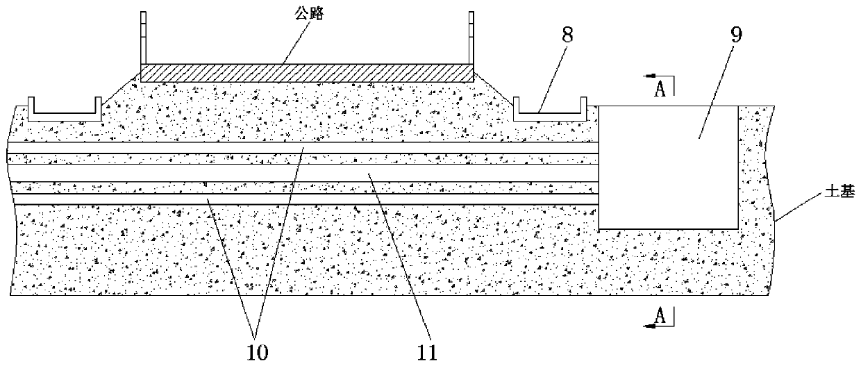
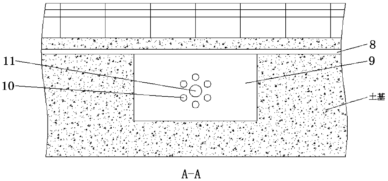
[0033] Such as Figures 1 to 5 As shown, the present embodiment provides a construction method for earthwork perforation below the highway drainage ditch, comprising the following steps:
[0034] Step 1: Excavate the foundation pit 9 on one side of the drainage ditch 8;
[0035] Step 2: In the foundation pit 9, drill a number of reinforcement holes 10 uniformly distributed in a circular array on the side of the foundation pit 9 through the guide pier and drilling equipment. After the reinforcement hole 10 of height, to reinforcement hole 10 internal pumping, until water level drops below reinforcement hole 10, then reinforcement hole 10 is grouted, after the cement slurry in reinforcement hole 10 is solidified, plan the soil foundation at the bottom of guide pier, until The height of the guide pier is lowered to a suitable position, and then a reinforcement hole 10 of the next height is drilled through the guide pier, and the above operation is repeated to perform pumping and...
Embodiment 2
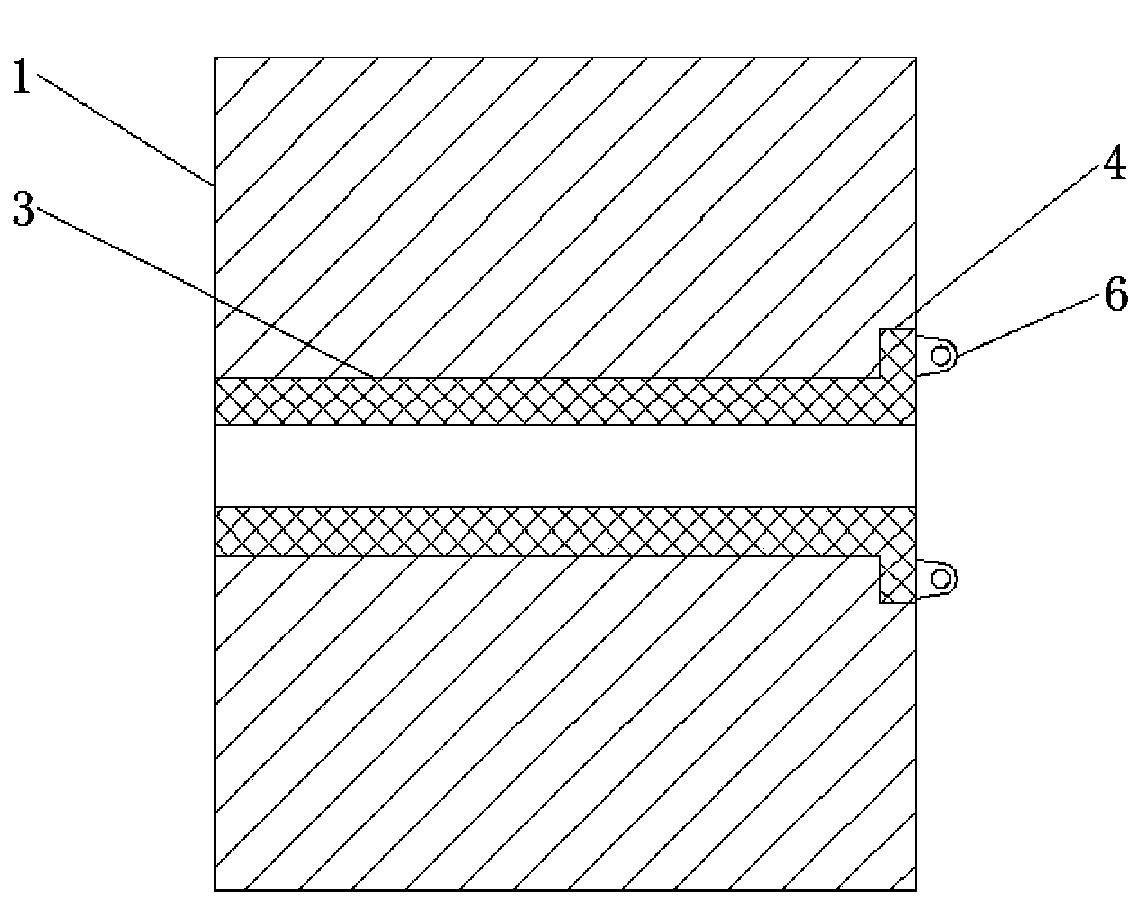
[0043] Such as Figures 3 to 5 As shown, the present embodiment is further optimized on the basis of Embodiment 1. Specifically, the guide pier includes a pier body 1, and a number of evenly distributed guide holes 2 of equal height are provided inside the pier body 1. The holes 2 are all provided with an adjusting sleeve 3 that cooperates with the guide hole 2, and one end of the adjusting sleeve 3 is provided with a number of outwardly protruding blocks 4, and the plurality of blocks 4 are arranged in a circular array with the center of the guide hole 2 as the center of the circle. The side of the pier body 1 is provided with a number of slots 5 that cooperate with the blocks 4, and the slots 5 communicate with the guide holes 2.
[0044] In this embodiment, when using the guide pier, the diameter of the guide hole is limited by adjusting the sleeve, and the inner diameter of the adjustment sleeve matches the diameter of the drill pipe in the drilling equipment. , select th...
Embodiment 3
[0046] Such as Figures 3 to 5 As shown, this embodiment is further optimized on the basis of embodiment 2. Specifically, the pier body 1 is square as a whole, and the pier body 1 is made of concrete, which has low manufacturing difficulty and low manufacturing cost.
[0047] The clamping block 4 and the adjusting sleeve 3 are integrally formed or welded, which is convenient for processing and has low manufacturing difficulty. The materials of the clamping block 4 and the adjusting sleeve 3 are both steel or iron, which meet the requirements for use strength. The number of 4 is 3-6, satisfying the stability of the clamping structure.
[0048] The outside of the clamping block 4 is connected with a lifting lug 6, and one clamping block 4 is only connected to one lifting lug 6, and there are at least two lifting lugs 6. After use, the lifting lug 6 is hung on a hook, and the other end of the hook passes through The zipper is connected to a mechanical device (such as a trailer),...
PUM
| Property | Measurement | Unit |
|---|---|---|
| Aperture | aaaaa | aaaaa |
| Diameter | aaaaa | aaaaa |
Abstract
Description
Claims
Application Information
 - R&D
- Intellectual Property
- Life Sciences
- Materials
- Tech Scout
- Unparalleled Data Quality
- Higher Quality Content
- 60% Fewer Hallucinations
Browse by: Latest US Patents, China's latest patents, Technical Efficacy Thesaurus, Application Domain, Technology Topic, Popular Technical Reports.
© 2025 PatSnap. All rights reserved.Legal|Privacy policy|Modern Slavery Act Transparency Statement|Sitemap|About US| Contact US: help@patsnap.com


