Heat shielding assembly, crystal pulling furnace system and working method of crystal pulling furnace system

A heat shielding and crystal pulling furnace technology, which is applied in chemical instruments and methods, self-melting liquid pulling method, crystal growth, etc., can solve the problems of ineffective energy storage and heat insulation, ineffective effect, and large central opening size, etc. problems, achieve the effects of saving consumables, promoting rapid melting, and increasing the axial temperature gradient

Active Publication Date: 2019-06-21
XIAN ESWIN MATERIAL TECH CO LTD +1
View PDF6 Cites 2 Cited by
  • Summary
  • Abstract
  • Description
  • Claims
  • Application Information

AI Technical Summary

Problems solved by technology

[0003] Generally speaking, in order to control the temperature gradient change in the crystal pulling furnace and to affect the growth of good quality single crystal silicon rods, generally in the crystal pulling furnace furnace A bowl-like heat shield assembly is provided, and the upper and lower ends are in the shape of concentric circle openings. It mainly includes an external reflector and an internal reflector, which are mainly used for temperature control during the equal-diameter growth of single crystal silicon rods, but for The effect is not obvious when polysilicon raw materials are melted, especially when it comes to the growth of large-sized monocrystalline silicon rods, the size of the central opening becomes significantly larger, which cannot effectively store energy and heat insulation

Method used


Image

  • Heat shielding assembly, crystal pulling furnace system and working method of crystal pulling furnace system
  • Heat shielding assembly, crystal pulling furnace system and working method of crystal pulling furnace system
  • Heat shielding assembly, crystal pulling furnace system and working method of crystal pulling furnace system

Examples


Embodiment Construction

[0033] In order to make the purpose, technical solutions and advantages of the embodiments of the present invention more clear, the following will clearly and completely describe the technical solutions of the embodiments of the present invention in conjunction with the drawings of the embodiments of the present invention. Apparently, the described embodiments are some, not all, embodiments of the present invention. All other embodiments obtained by those skilled in the art based on the described embodiments of the present invention belong to the protection scope of the present invention.

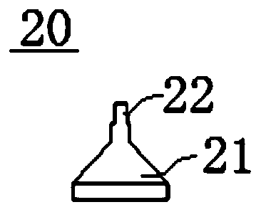
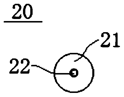
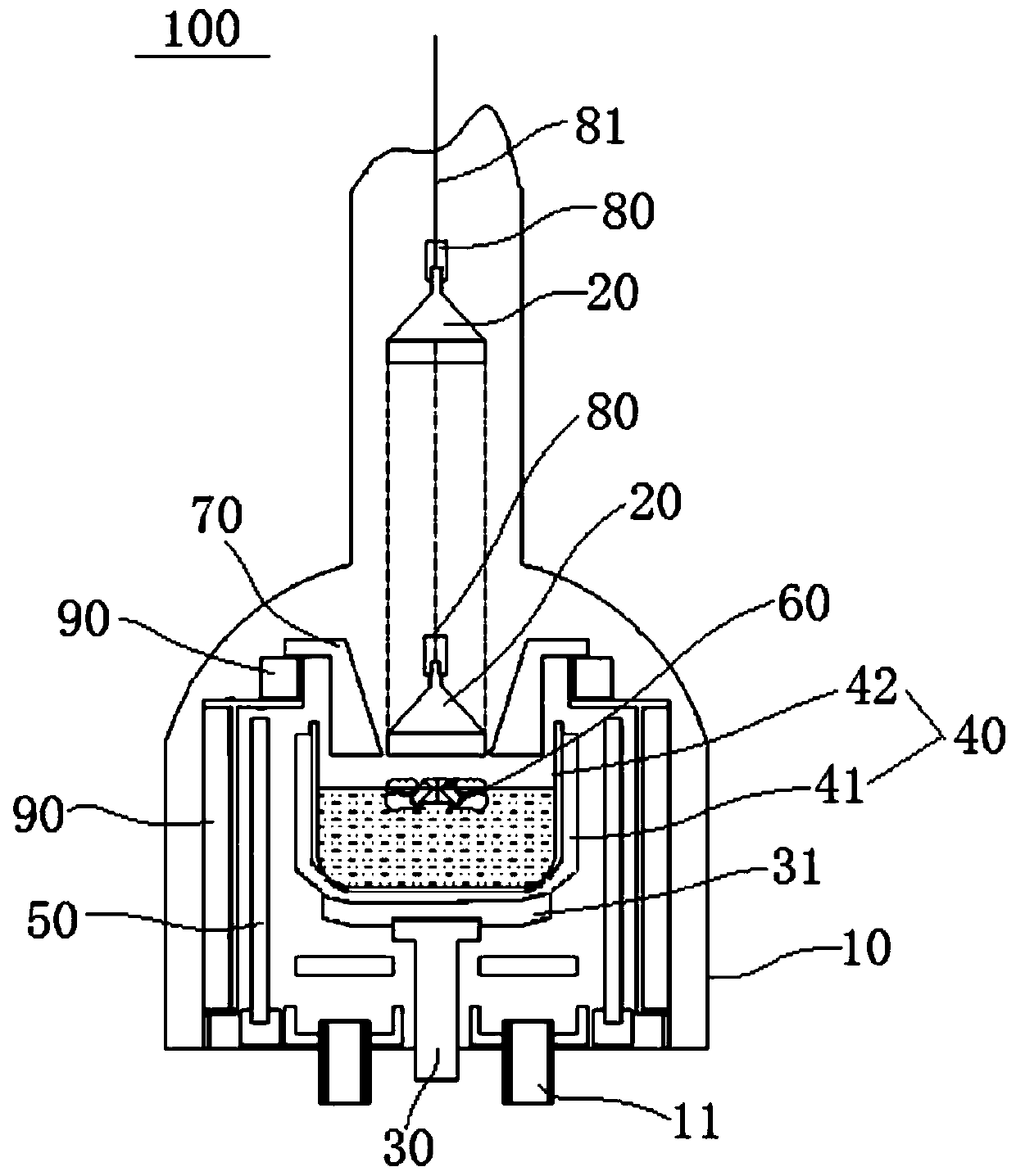
[0034] The heat shield assembly 20 according to the embodiment of the present invention will be described in detail below with reference to the accompanying drawings.

[0035] like Figure 1 to Figure 3 As shown, the heat shield assembly 20 according to the embodiment of the present invention is arranged in the hearth of the crystal pulling furnace, and the hearth of the crystal pulling fu...


PUM


Abstract

The invention provides a heat shielding assembly, a crystal pulling furnace system and a working method of the crystal pulling furnace system. The heat shielding assembly is arranged inside a furnacehearth of a crystal pulling furnace, the furnace hearth of the crystal pulling furnace is internally provided with a crucible for holding materials and a seed chuck, and the seed chuck is used for fixing a seed crystal or the heat shielding assembly. The heat shielding assembly comprises a heat shielding body and a reverse heat radiation material piece, wherein one end of the heat shielding body faces the crucible, the other end of the heat shielding body is detachably connected with the seed chuck, and the seed chuck can move so as to drive the heat shielding body to move in the axial direction of the furnace hearth of the crystal pulling furnace through a pulling rope; the reverse heat radiation material piece is arranged on the side, facing the crucible, of the heat shielding body. According to the heat shielding assembly provided by the invention, high-temperature heat radiation of reflection material melt liquid can be reflected effectively, the axial temperature gradient inside the crystal pulling furnace is increased, and rapid fusion of the material is promoted. The heat shielding assembly is in a cap form, and sputtering liquid during material fusion can be accommodated and returned back into the original melt liquid.

Description

technical field [0001] The invention relates to the technical field of monocrystalline silicon manufacturing, and more specifically, to a heat shield assembly, a crystal pulling furnace system and a working method of the crystal pulling furnace system. Background technique [0002] As methods for manufacturing single crystal silicon, there are zone melting method and Czochralski method. In the prior art, the Czochralski method (ie, CZ method) is usually used to prepare single crystal silicon. The CZ method is to house the polysilicon raw material in a quartz crucible set in the hearth of the crystal pulling furnace, heat and melt it through a graphite heater, and then put a rod-shaped seed crystal (called a seed crystal) with a diameter of only 10mm in contact with the polysilicon molten liquid surface , at the appropriate temperature required by the process, the silicon atoms in the melt will follow the silicon atom arrangement structure of the seed crystal to form regular ...

Claims


Application Information

Patent Timeline
Patent Type & Authority Applications(China)
IPC IPC(8): C30B15/00C30B29/06
Inventor 潘浩全弘湧全铉国兰洵张鹏举同嘉锡
Owner XIAN ESWIN MATERIAL TECH CO LTD
Why Eureka
Try Eureka