Radio frequency ablation catheter and radio frequency ablation system
A radiofrequency ablation and catheter technology, which is applied in the field of medical devices, can solve the problems of inability to closely fit the ablated tissue, poor ability of ablation electrodes to pass lesions, and large size of ablation electrodes, so as to meet the needs of clinical use and improve the ability to pass lesions. , the effect of improving the success rate of ablation
- Summary
- Abstract
- Description
- Claims
- Application Information
AI Technical Summary
Problems solved by technology
Method used
Image
Examples
Embodiment 1
[0033] In this embodiment, the radiofrequency ablation catheter includes a lumen body and a flexible electrode, the flexible electrode is disposed on the wall of the lumen body, and the lumen body is a catheter body or a balloon disposed outside the catheter body.
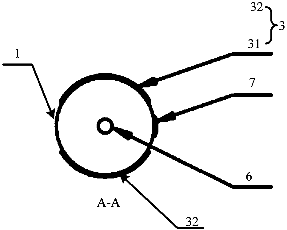
[0034] Please refer to figure 1 , which is a schematic diagram of the structure of the radiofrequency ablation catheter in an embodiment of the present invention, such as figure 1 As shown, the radiofrequency ablation catheter includes: a balloon 1, a catheter body 2 and a flexible electrode 3, the balloon 1 is arranged on the outside of the catheter body 2, and the flexible electrode 3 is arranged on the outside of the balloon 1 Therefore, the flexible electrode 3 can be folded or expanded to a certain shape and position along with the balloon 1, so as to ablate the biological tissue at the corresponding position.
[0035] The core idea of the radiofrequency ablation catheter of the present invention is to use ...
example 11
[0044] In this embodiment, the balloon 1 is an ordinary flat structure, and the material of the balloon 1 is a nylon / Pebax (block polyether amide resin) blend material, and the length of the flat section of the balloon 1 after expansion is 40.0 mm. , with a diameter of 4.0mm. The graphene electrode is a sheet-like structure with a square cross section, wherein the graphene electrode has a side length of 1 mm and a thickness of 30 μm. The cable joint 6 is connected to the graphene electrode through the third interface 53 of the connector 5 through at least one electrode lead 4, and the electrode lead 4 is made of one or more materials in stainless steel, platinum, iridium, carbon fiber or conductive polymer One end of the electrode wire 4 is fixedly connected to the edge of the graphene electrode by brazing, and then the graphene electrode and the electrode wire 4 are bonded and fixed in the middle of the outer surface of the straight section of the balloon 1 by conductive glue...
Embodiment 2
[0046] Please refer to image 3 The difference between the second embodiment and the first embodiment lies in the position of the temperature measuring component 7 relative to the positive and negative electrodes 32 in the flexible electrode 3 . The temperature measurement component 7 in the first embodiment is set at the specific position near the flexible electrode 3 refers to: the measurement component is set between the positive electrode 31 and the negative electrode 32; The specific location where the temperature measuring component 7 is disposed near the flexible electrode 3 refers to: the temperature measuring component 7 is disposed on one side of the positive electrode 31 and / or the negative electrode 32 . In other words, the location where the temperature measurement component 7 is set includes not limited to between the positive electrode 31 and the negative electrode 32, as long as it is near the flexible electrode 3, it can sense that the flexible electrode 3 is ...
PUM
| Property | Measurement | Unit |
|---|---|---|
| Thickness | aaaaa | aaaaa |
| Diameter | aaaaa | aaaaa |
| Length | aaaaa | aaaaa |
Abstract
Description
Claims
Application Information
 - R&D
- Intellectual Property
- Life Sciences
- Materials
- Tech Scout
- Unparalleled Data Quality
- Higher Quality Content
- 60% Fewer Hallucinations
Browse by: Latest US Patents, China's latest patents, Technical Efficacy Thesaurus, Application Domain, Technology Topic, Popular Technical Reports.
© 2025 PatSnap. All rights reserved.Legal|Privacy policy|Modern Slavery Act Transparency Statement|Sitemap|About US| Contact US: help@patsnap.com


