Shale gas drilling wastewater treatment method

A technology of drilling wastewater and treatment method, which is applied in mining wastewater treatment, water/sewage multi-stage treatment, water/sludge/sewage treatment, etc. High volume, complex chemical composition and other problems, to achieve the effect of convenient boiler maintenance, reduction of ammonia nitrogen content, and simple process flow

Inactive Publication Date: 2019-06-25
重庆市涪陵页岩气环保研发与技术服务中心
View PDF6 Cites 12 Cited by
  • Summary
  • Abstract
  • Description
  • Claims
  • Application Information

AI Technical Summary

Problems solved by technology

[0003] ① Large chroma, high viscosity, complex chemical composition, generally dark brown or black viscous liquid, poor biochemical treatment;
[0004] ② High water content, not easy to dehydrate, pH is generally greater than 7;
[0006] ④ Due to the high oil content of certain special drilling fluids, the oil content in drilling wastewater is also high;
[0008] As an emerging industry in China, shale gas mining has a large difference in water quality between its drilling wastewater and conventional natural gas drilling wastewater. At present, there are various methods for treating various wastewater, including coagulation sedimentation, chemical oxidation, and physical adsorption. According to environmental protection requirements, different wastewater methods and their combinations can be used to obtain different treatment effects, but there are few technologies for targeted treatment of shale gas drilling wastewater. Therefore, it is necessary to seek economically feasible and technically feasible The treatment technology of drilling wastewater is imperative

Method used


Image

  • Shale gas drilling wastewater treatment method
  • Shale gas drilling wastewater treatment method

Examples


Embodiment 1

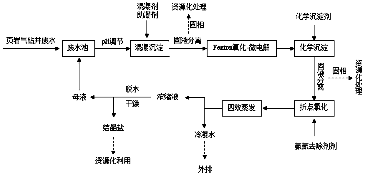
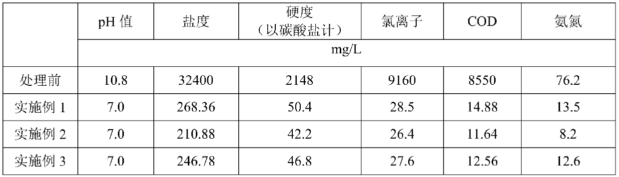
[0038] Embodiment 1, a kind of shale gas drilling wastewater treatment method comprises the following steps:

[0039] Step 1: Introduce the drilling wastewater in the wastewater tank into the coagulation sedimentation tank through the pipeline, adjust the pH value of the drilling wastewater in the coagulation sedimentation tank to 8, add coagulant and coagulant aid, and the amount of coagulant added is 0.8kg / m 3 , the amount of coagulant aid added is 0.025kg / m 3 , stirred at a slow speed and then left to settle, and then solid-liquid separation was carried out to obtain the primary wastewater for the first removal of COD and SS. Recycling of materials;

[0040] Step 2: Adjust the pH value of the primary wastewater in the Fenton oxidation-micro-electrolytic cell to 2, add hydrogen peroxide and Fe / C filler, and add 30% hydrogen peroxide to 4L / m 3 , the amount of Fe / C filler added is 300kg / m 3 , and pump air in, the air-water ratio is controlled to be 8:1, and after 2 hours of...

Embodiment 2

[0044] Embodiment 2, a kind of shale gas drilling wastewater treatment method, comprises the following steps:

[0045] Step 1: Introduce the drilling wastewater in the waste water pool into the coagulation sedimentation tank through the pipeline, and add coagulant and coagulant aid to the drilling wastewater 9 in the coagulation sedimentation tank, and the amount of coagulant added is 1kg / m 3 , the amount of coagulant aid added is 0.05kg / m 3 , stirred at a slow speed and then left to settle, and then solid-liquid separation was carried out to obtain the primary wastewater for the first removal of COD and SS. Recycling of materials;

[0046] Step 2: Adjust the pH value of the primary wastewater in the Fenton oxidation-micro-electrolytic cell to 3, add hydrogen peroxide and Fe / C filler, and add 30% hydrogen peroxide to 6L / m 3 , the amount of Fe / C filler added is 500kg / m 3 , and pump in the air, the air-water ratio is controlled at 5:1, and after 2 hours of reaction, the secon...

Embodiment 3

[0050] Embodiment 3, a kind of shale gas drilling wastewater treatment method, comprises the following steps:

[0051] Step 1: Introduce the drilling wastewater in the wastewater tank into the coagulation sedimentation tank through the pipeline, adjust the pH value of the drilling wastewater in the coagulation sedimentation tank to 11, add coagulant and coagulant aid, and the amount of coagulant added is 1.2kg / m 3 , the amount of coagulant aid added is 0.075kg / m 3 , stirred at a slow speed and then left to settle, and then solid-liquid separation was carried out to obtain the primary wastewater for the first removal of COD and SS. Recycling of materials;

[0052] Step 2: Adjust the pH value of the primary wastewater in the Fenton oxidation-micro-electrolytic cell to 5, add hydrogen peroxide and Fe / C filler, and add 30% hydrogen peroxide to 8L / m 3 , the amount of Fe / C filler added is 500kg / m 3 , and pump air in, the air-water ratio is controlled at 10:1, and after 2 hours of...


PUM

PropertyMeasurementUnit
hardnessaaaaaaaaaa

Abstract

The invention provides a shale gas drilling wastewater treatment method. The Shale gas drilling wastewater treatment method comprises the following steps that S1, the pH of drilling wastewater is adjusted to be 8-11, a coagulant and a coagulant aid are added, after uniform stirring, static settlement is conducted, and then solid-liquid separation is conducted; S2, the pH of clear liquid obtained through solid-liquid separation in the step S1 is adjusted to be 2-5, hydrogen peroxide and a Fe / C filler are added, and air is pumped in for reaction for 1.5-2 h; S3, the pH of the wastewater treatedin the step S2 is adjusted to be 9-11, a chemical precipitation agent is added, the temperature is controlled to be 80 DEG C, uniform stirring is conducted, reaction is conducted for 20-40 min, and then solid-liquid separation is conducted; S4, the pH of clear liquid obtained through solid-liquid separation in the step S3 is adjusted to be 7-9, an ammonia-nitrogen removing agent is added, and reaction is conducted for 20-30 min; and S5, the wastewater treated in the step S4 is treated through a low-temperature vacuum evaporation method, and thus condensed water and concentrated liquor are obtained. According to the shale gas drilling wastewater treatment method, the shale gas drilling wastewater is sequentially subjected to coagulating sedimentation, Fenton oxidation-microelectrolysis, chemical precipitation, ammonia-nitrogen removing and four-effect evaporation treatment, the conventional indexes in the treated drilling wastewater can reach the primary standard of the wastewater comprehensive discharging standard.

Description

technical field [0001] The invention belongs to the technical field of drilling wastewater treatment, and in particular relates to a treatment method for shale gas drilling wastewater. Background technique [0002] Shale gas drilling wastewater has a complex composition and contains various components in the mud. The main pollutants include: suspended solids mainly bentonite, petroleum, heavy metals, organic matter and chlorides, etc. The composition and concentration vary with the mud system, Drilling well depth and drilling formation change, it is a mixture of mud dilution and oil. In general, shale gas drilling wastewater has the following characteristics: [0003] ① Large chroma, high viscosity, complex chemical composition, generally dark brown or black viscous liquid, poor biochemical treatment; [0004] ② High water content, not easy to dehydrate, pH is generally greater than 7; [0005] ③ Contains more solid substances, such as clay, bentonite, rock debris, etc.; ...

Claims


Application Information

Patent Timeline
Patent Type & Authority Applications(China)
IPC IPC(8): C02F9/10E21B21/06C02F103/10
Inventor 王丹金吉中梅绪东徐烽淋刘璞王朝强张春熊德明张思兰
Owner 重庆市涪陵页岩气环保研发与技术服务中心
Why Eureka
Try Eureka