Array radiation level-sensing device and measuring method thereof

A material level meter and array technology, applied in the field of material level meter, can solve the problems of small measurement range, long response time and poor directionality of passive nuclear material level meter, so as to solve the problem of inaccurate measurement, strong performance expansion capability, The effect of reducing the intensity of radioactivity

Pending Publication Date: 2019-07-05
上海沃纳机电设备有限公司
View PDF0 Cites 0 Cited by
  • Summary
  • Abstract
  • Description
  • Claims
  • Application Information

AI Technical Summary

Problems solved by technology

[0005] 1. Poor time characteristics
Due to the long single pulse time of the photomultiplier tube, the response time of the passive nuclear level gauge that generates material level data after a large number of sample calculations is relatively long
When measuring the material level of a container with a relatively fast operation process, even in the fastest response time mode, the measurement data of the passive nuclear material level gauge seriously lags behind the actual working conditions, such as a warehouse pump that feeds in a few seconds and comes out in a few seconds , the passive nuclear level gauge cannot perform real-time control and measurement
[0006] 2. Poor directionality
When measuring the material level, it is impossible to distinguish the actual position of the material level in the container, such as up, down, left, and right. You only know the material level, but you don’t know where the material is.
[0007] 3. Large size and heavy weight
As a result, the actual measurement range of the passive nuclear level gauge is very small
Through multi-probe passive nuclear level gauges or multiple passive nuclear level gauges connected in series to form a large range of measurement, although the measurement range problem is solved, the cost is high

Method used


Image

  • Array radiation level-sensing device and measuring method thereof
  • Array radiation level-sensing device and measuring method thereof
  • Array radiation level-sensing device and measuring method thereof

Examples


Embodiment approach 1

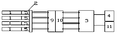
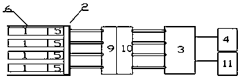
[0030] This embodiment provides an array radiation level gauge, such as figure 1 As shown, it mainly includes four scintillation crystals 1 and an array photoelectric conversion and multiplication unit 2 composed of four micro-devices 5 that can independently complete photoelectric conversion and multiplication, and also includes a filter 9, an amplifier 10, an operation processor 3 and Output unit 4; in the present embodiment, the arrayed photoelectric conversion and multiplication unit 2 preferably uses silicon photomultiplier tubes in an array layout, a microchannel plate photomultiplier tube, a microsphere photomultiplier tube or an avalanche diode in an array layout; Each scintillation crystal 1 is coupled with the array type photoelectric conversion and multiplication unit 2, the array type photoelectric conversion and multiplication unit 2 has four electrical signal channels, that is, a micro device 5 has an electrical signal channel; the input end of the filter 9 passes...

Embodiment approach 2

[0043] This embodiment is a further improvement of Embodiment 1. The main improvement is that in Embodiment 1, since there are cosmic background radiation noise signals around the scintillation crystal 1, these cosmic background radiation noise signals will lead to the final measured material level data Inaccurate, therefore, the array radiation level gauge in this embodiment also includes a radiation shielding component 6, and the radiation shielding component 6 is preferably a cover made of lead skin in practical applications. The radiation shielding component 6 is used to shield the cosmic background radiation noise signal around the scintillation crystal 1 in the non-measurement direction, so as to make the measurement result of the level gauge more accurate.

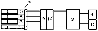
[0044] The radiation shielding part 6 can only cover the non-radiation receiving parts of the four scintillation crystals 1, such as figure 2 , or block the non-radiation-receiving parts of the four scintillation c...

Embodiment approach 3

[0047] This embodiment is a further improvement of Embodiment 2, such as Figure 5 , the array radiation level gauge in this embodiment further includes a noise shielding cover 7, and the noise shielding cover 7 completely covers and blocks any one of the four micro-devices 5. The main purpose of adding the noise shield 7 is: the arithmetic processor 3 can use the signal generated by the micro-device 5 covered by the noise shield 7 as the background noise signal, and the material level of the generated material in step S4 in the first embodiment In the process of data or image, the background noise signal can be used to correct the signals measured by other micro devices 5, so as to generate more accurate material level related data.

[0048] Apart from this, this embodiment is completely the same as Embodiment 2, and will not be repeated here.


PUM


Abstract

The invention relates to the field of level-sensing devices, and discloses an array radiation level-sensing device and a measuring method thereof. An array type photoelectric conversion and multiplying part (2) consists of at least two micro-devices (5) which can independently accomplish photoelectric conversion and multiplying; scintillating crystals (1) are coupled to the array type photoelectric conversion and multiplying part (2); the array type photoelectric conversion and multiplying part (2) has at least one electric signal channel; the input end of an arithmetic processor (3) is connected to the electric signal channels; and the input end of an output part (4) is connected to the output end of the arithmetic processor (3). Compared with the prior art, the level-sensing device realizes the functions and performance that existing level-sensing devices cannot accomplish; the level-sensing device has extremely strong performance extensibility; the size of the level-sensing device can be greatly reduced; and the time characteristics, direction characteristics and spatial resolving power of the level-sensing device can be enhanced, the measuring ranges of single level-sensing device can be increased, so that the measuring can be more accurate and reliable.

Description

technical field [0001] The invention relates to the field of material level gauges, in particular to an array radiation level gauge and a measuring method thereof. Background technique [0002] In the field of material level measurement, the non-contact measurement method is not easily affected by harsh environments such as falling material inside the container, high temperature, steam, etc. because it does not contact the material. Compared with radar, laser, ultrasonic, machine vision and other non-contact level gauges that need to be placed inside the container, nuclear level gauges and passive nuclear level gauges are placed outside the container, directly penetrating the container under non-destructive conditions The shell completes the measurement, which is a necessary choice for many working conditions. However, in actual production and application, both the nuclear material level gauge and the passive nuclear material level gauge have certain defects, which cannot g...

Claims


Application Information

Patent Timeline
Patent Type & Authority Applications(China)
IPC IPC(8): G01F23/288
CPCG01F23/288
Inventor 胡桂标
Owner 上海沃纳机电设备有限公司
Why Eureka
Try Eureka