
An indirect air-cooling unit high back pressure heating system and adjustment method

A technology for heating systems and air-cooling units, which is applied in heating systems, space heating and ventilation, hot water central heating systems, etc. The effect of reducing the thermal area, reducing the temperature difference of the lift, and reducing the transformation investment

Active Publication Date: 2020-11-06
晟源高科(北京)科技有限公司
View PDF3 Cites 0 Cited by
  • Summary
  • Abstract
  • Description
  • Claims
  • Application Information

AI Technical Summary

Problems solved by technology

[0009] 1. The condensers are operated with hot network water on one side and circulating water on the other side, resulting in the inability to fully utilize the heating potential of the unit, and only use about half of the exhaust steam heating capacity
[0010] 2. If the hot plate heat exchanger is used for water-water heat exchange, the plate exchange area needs to be large, and the cost will increase greatly
[0011] 3. Due to the upper end difference of the plate heat exchanger, to ensure the same outlet water temperature, it is necessary to maintain a higher back pressure operation, which will affect more power generation due to the higher back pressure operation of the unit

Method used


Image

  • An indirect air-cooling unit high back pressure heating system and adjustment method
  • An indirect air-cooling unit high back pressure heating system and adjustment method
  • An indirect air-cooling unit high back pressure heating system and adjustment method

Examples


Embodiment Construction

[0033] Next, the present invention will be further described in conjunction with the accompanying drawings and specific embodiments.

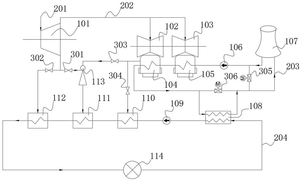
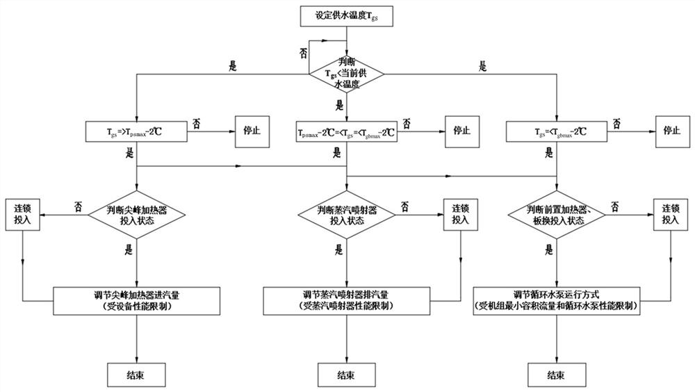
[0034] refer to Figure 1-2 ,in figure 1 It is a schematic diagram of the system composition of the indirect air-cooling unit high back pressure heating system of the present invention, figure 2 It is a control logic schematic diagram of the high back pressure heating system of the indirect air cooling unit of the present invention, wherein: the present invention provides a high back pressure heating system of the indirect air cooling unit, and the heating system mainly includes: the medium pressure cylinder 101 of the steam turbine, the first Low pressure cylinder 102 of the first steam turbine, low pressure cylinder 103 of the second steam turbine, high back pressure condenser 104, low back pressure condenser 105, circulating water pump 106, indirect air cooling tower 107, heat network plate heat exchanger 108, heat network circulating wate...


PUM


Abstract

The invention discloses an indirect air cooling unit high back pressure heat supplying system and an adjusting method. The system mainly comprises a steam turbine intermediate pressure cylinder, a steam turbine low pressure cylinder, a high back pressure steam condenser, a low back pressure steam condenser, a circulating water pump, an indirect air cooling tower, a thermal net plate type heat exchanging device, a thermal network circulating water pump, a front-mounted thermal net steam condenser, a steam jetting device steam condenser, a peak heating device, a vapour jetting device and the like. According to the system, first stage heating is conducted on thermal net back flowing water by using the thermal net plate type heat exchanging device, secondary heating is conducted on the thermalnet back flowing water by the front-mounted thermal net steam condenser, third-stage heating is conducted on the thermal net back flowing water by using the steam jetting device steam condenser, fourth-stage heating is conducted on the thermal net back flowing water by using the peak heating device, and the gradient utilization of the energy is achieved by four-stage heating of the whole system.The system has the advantages that the technological converting is simple, the cost is low, the converting on the steam turbine body is not needed, the defect of larger end difference of panel type heat exchanging device is overcome, compared with traditional indirect air cooling unit high back pressure heat supplying converting, the dead steam utilization rate of the unit after application is improved, and equipment initial investment is reduced.

Description

technical field [0001] The invention relates to a heat supply system, in particular to an indirect air-cooling unit high back pressure heat supply system and an adjustment method. Background technique [0002] In recent years, due to the country's emphasis on environmental protection and water conservation in the construction of power projects, air-cooled units using air as the cooling medium have developed rapidly in power construction. Air-cooled units are widely used in North China, Inner Mongolia, Xinjiang and other places in my country, effectively solving the problem of power generation in areas rich in coal and poor in water. With the operation and promotion of the air-cooling system of power stations in my country, the system has gradually reached a consensus on its advantages such as no need for cooling water, large heat transfer temperature difference, simple system, flexible and reliable air volume adjustment, strong corrosion resistance, and small footprint. Comp...

Claims


Application Information

Patent Timeline
Patent Type & Authority Patents(China)
IPC IPC(8): F24D3/02F28B1/02
CPCF24D3/02F28B1/02
Inventor 冯征殷培光吕一农崔青汝刘雁宾杨怀亮刘东远任子芳贾彦兵
Owner 晟源高科(北京)科技有限公司
Learn More