Underwater gravel foundation bed laying device and method

A laying device and foundation bed technology, which is applied in the field of underwater gravel foundation bed laying devices, can solve problems such as low construction accuracy, correcting riprap pipes, and high cost, and achieve the effect of facilitating overall movement and ensuring accuracy

Pending Publication Date: 2019-07-12
CCCC SECOND HARBOR ENG
View PDF8 Cites 5 Cited by
  • Summary
  • Abstract
  • Description
  • Claims
  • Application Information

AI Technical Summary

Problems solved by technology

The disadvantage of this method is that the cost is extremely expensive, and the pile legs need to be inserted into the groove of the tunnel foundation bed, which has a certain damage to the foundation
[0005] Chinese patent document CN107489154A records a construction method for leveling deep-sea foundation beds, which implements rock throwing through the movement of the hull. The existing problem is that the hull is affected by waves during the movement process, and the construction accuracy is not high.
However, with this scheme, after a construction area is completed, the hull needs to be moved as a whole and repositioned. In the repositioning process, it is necessary to rely on the positioning accuracy of GPS, which has the problems of slow positioning speed and poor positioning accuracy.
Further, it also records the scheme of controlling the balance pipe to expand and contract repeatedly through the hydraulic cylinder to adjust the stroke, but due to the influence of water flow and wind and waves, it is difficult to keep the riprap pipe vertical. Although the inclinometer is recorded in the manual, the It does not record how to correct the inclination of the riprap pipe according to the inclination to ensure the flatness of the foundation bed
Further, since the hydraulic cylinders are located underwater, and each hydraulic cylinder has oil inlet and oil return pipes, it is very difficult to accurately control multiple hydraulic cylinders, and many hydraulic oil pipes make the lifting control of the riprap pipe very troublesome
Furthermore, the above-mentioned document also records that the leveling head is used to scrape the foundation bed, but as the length of the riprap tube increases, the bending deformation of the riprap tube increases, and the leveling accuracy of this solution is difficult to control

Method used


Image

  • Underwater gravel foundation bed laying device and method
  • Underwater gravel foundation bed laying device and method
  • Underwater gravel foundation bed laying device and method

Examples


Embodiment 1

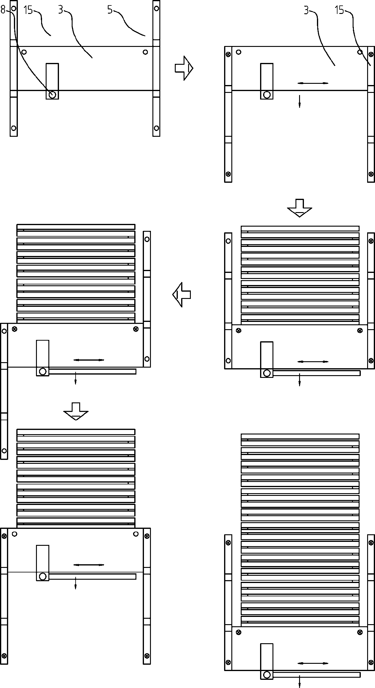
[0058] Such as Figure 1~4 Among them, an underwater gravel bed laying device includes a hull 3, on which a transport trolley 13 is arranged, and the transport trolley 13 is driven by a driving device to slide along the length direction of the hull 3, and on the transport trolley 13 is provided with a slide The top of the chute is provided with a feeding port 8, and the bottom of the chute is close to the bottom of the water; at least one conveyor belt for feeding the trolley 13 is also provided;

[0059] The position of hull 3 bow and stern is provided with buoyant tank slide rail 15, and buoyant tank slide rail 15 is slidably connected with hull, is provided with liftable positioning pile 5 on two buoyant tank slide rails 15 and hull 3;

[0060] Described pontoon slide rail 15 is folding structure, and the termination of pontoon slide rail 15 is folded on the side of hull 3 when moving, and during construction, the termination of pontoon slide rail 15 is launched. With this...

Embodiment 2

[0095] A method of using the above-mentioned underwater crushed stone bed laying device, comprising the following steps:

[0096] S1, the hull 3 moves to the design position, and uses GPS or Beidou system to locate the position of the chute on the horizontal plane;

[0097] The pontoon slide rail 15 is launched so that the hull 3 is positioned at the initial position of the pontoon slide rail 15; the positioning pile 5 on the pontoon slide rail 15 is driven into the bottom of the water;

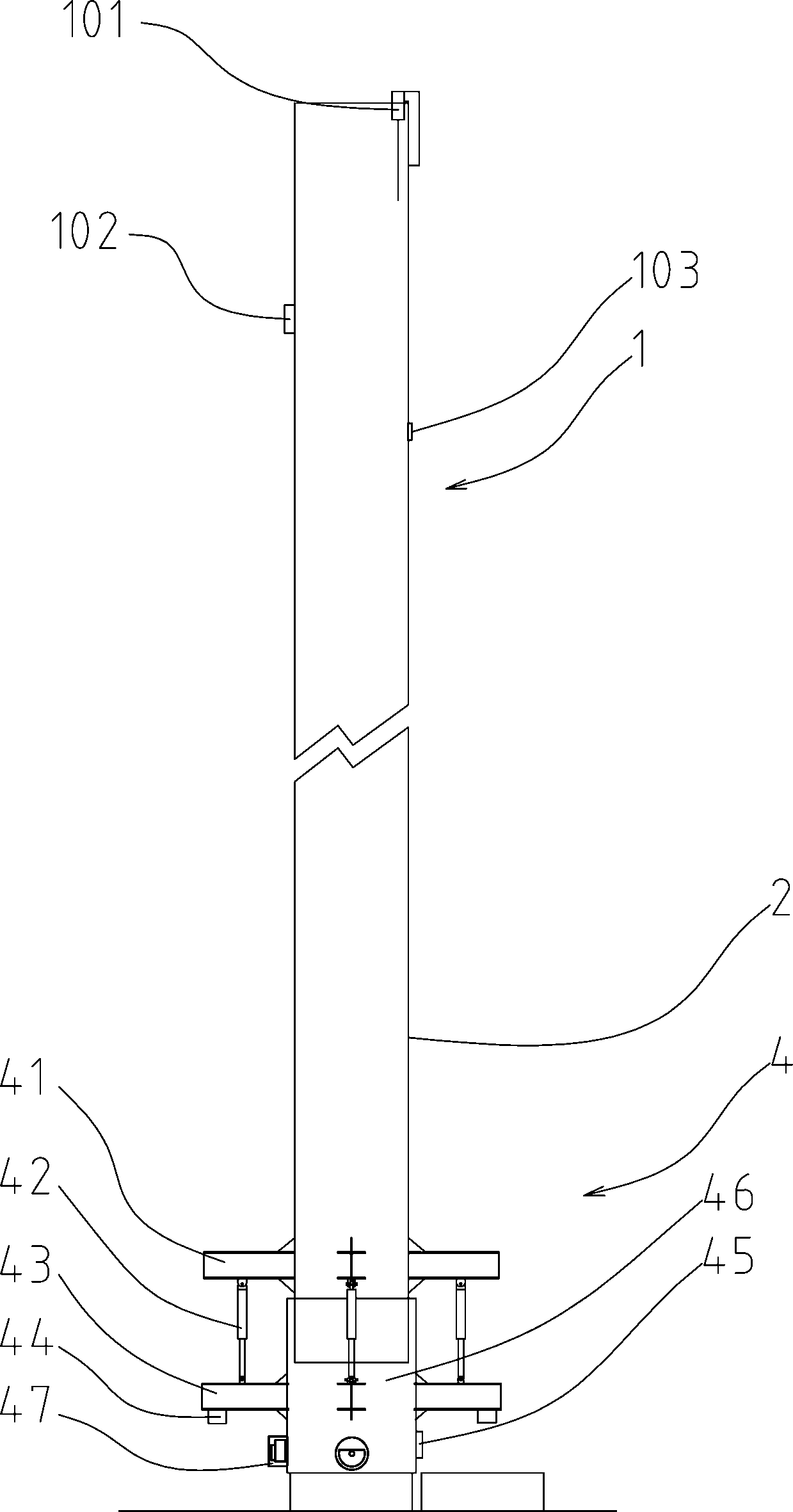
[0098] S2. Control the elevation position of the discharge port at the bottom of the chute by adjusting the lift of the chute;

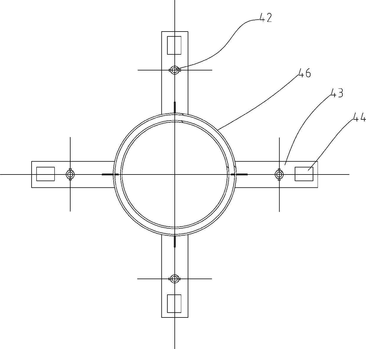
[0099] S3, the bottom of the chute is provided with a discharge opening adjustment device 4, and an inclination adjustment oil cylinder 42 is provided in the discharge opening adjustment device 4 to adjust the horizontality of the discharge opening at the lowermost end of the chute;

[0100] S4. Fill stones into the chute through the conveyor belt. When the stone r...


PUM


Abstract

The invention provides an underwater gravel foundation bed laying device and method. The underwater gravel foundation bed laying device comprises a hull, wherein a transportation trolley is arranged on the hull, the transportation trolley is driven by a driving device to slide in the length direction of the hull, a sliding tube is arranged on the transportation trolley, a material conveying port is formed in the top end of the sliding tube, and the bottom end of the sliding tube is close to the bottom of the water. The underwater gravel foundation bed laying device is further provided with atleast one conveyor belt for feeding the transportation trolley; buoyancy tank sliding rails are arranged at the positions of a ship bow and a stern of the hull, the buoyancy tank sliding rails are slidably connected with the hull, and positioning columns which can be lifted and lowered are arranged on the two buoyancy tank sliding rails and the hull; and the buoyancy tank sliding rails are of a folded structure. By adopting a scheme in which two foldable buoyancy tank sliding rails and the hull are alternately positioned through the positioning columns and relatively slid, after the riprap construction in an area is completed, the reciprocating movement of the positioning columns and the hull can achieve precise guided continuous movement, the condition that the hull is positioned every time the hull is moved is avoided, and high-precision continuous Z-shaped riprap paving construction is achieved through the sliding tube.

Description

technical field [0001] The invention relates to the field of underwater engineering construction, in particular to an underwater gravel bed laying device and method. Background technique [0002] The immersed tube method is a construction method for building tunnels under water. Immersed tube tunnel is an underwater tunnel constructed by floating several prefabricated sections to the sea surface (river surface) site, and sinking and installing them one by one in the dredged foundation trench. In order to avoid local high points of the foundation, the bottom plate of the immersed tube is evenly stressed, and a high-precision leveled gravel cushion is designed between the bottom plate and the foundation as the foundation bed, and a special gravel cushion laying ship with high leveling accuracy is required for construction. [0003] The representative ship is the dynamic positioning straight drop pipe riprap ship "FLINTSTONE" under the DEME group, which is the largest riprap s...

Claims


Application Information

Patent Timeline
Patent Type & Authority Applications(China)
IPC IPC(8): E02D15/10E02B3/00
CPCE02D15/10E02B3/00
Inventor 张鸿杨秀礼翟世鸿华晓涛冯先导徐杰程茂林王聪刘修成吴中正夏昊孟奎朱明清
Owner CCCC SECOND HARBOR ENG
Why Eureka
Try Eureka