
Carbon circulating system and method based on ammonia-process decarburization and electrocatalytic reduction utilization

A technology of circulation system and catalytic system, which is applied in the field of carbon cycle, green energy application and decarbonization, can solve the problems of economic limitation and large electric energy, and achieve the effect of improving capture efficiency and solving overcapacity

Inactive Publication Date: 2019-07-19
HARBIN INST OF TECH
View PDF3 Cites 1 Cited by
  • Summary
  • Abstract
  • Description
  • Claims
  • Application Information

AI Technical Summary

Problems solved by technology

Due to the large amount of electric energy required, the economy is limited, and the raw material carbon dioxide used for catalytic reduction must be high-purity carbon dioxide
Therefore, the technology is limited to laboratory research and mechanism research

Method used


Image

  • Carbon circulating system and method based on ammonia-process decarburization and electrocatalytic reduction utilization
  • Carbon circulating system and method based on ammonia-process decarburization and electrocatalytic reduction utilization

Examples


Embodiment Construction

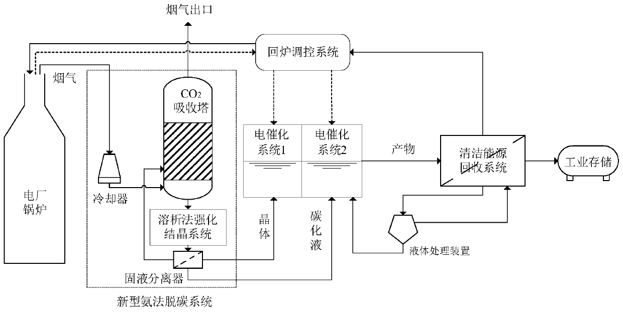
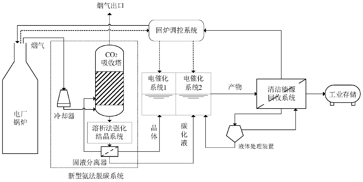
[0026] A carbon circulation system based on ammonia decarburization and electrocatalytic reduction utilization according to the present invention includes: ammonia decarburization system, electrocatalytic reduction system, clean energy recovery system and furnace return control system;

[0027] The new ammonia decarbonization system includes flue gas cooling device, CO 2Absorption tower, elution method enhanced crystallization system, and solid-liquid separation device; boiler flue gas enters the CO after being cooled by the cooler 2 Absorption tower, CO 2 Absorber absorbs CO using novel ammonia decarbonization method 2 , and pass the solution into the elution enhanced crystallization system for CO 2 The enhanced crystallization of the absorption and the recycling of the absorbent; the product crystals and carbonized liquid are separated by a solid-liquid separation device and sent to the electrocatalytic system 1 and electrocatalytic system 2 respectively. The remaining fl...


PUM


Abstract

The invention discloses a carbon circulating system and method based on ammonia-process decarburization and electrocatalytic reduction utilization, and belongs to the technical field of green energy application. The invention aims to solve the problems of capture, utilization, conversion and storage of carbon dioxide. The system comprises an ammonia-process decarburization system, an electrocatalytic reduction system, a clean energy recovery system and a remelting regulation and control system. Flue gas at the tail end of a boiler of a thermal power generating unit is introduced into the ammonia-process decarburization system for CO2 removal, generated ammonium bicarbonate crystals and carbonized liquid are catalytically reduced through the electrocatalytic reduction system to generate clean energy sources such as CO and formic acid after treatement; after recovered and treated by the clean energy recovery system, the clean energy is used for remelting regulation and control and for providing chemical industrial raw materials; and when the thermal power generating unit is in high-load operation, the remelting regulation and control system provides clean energy to enter a furnace, and when the thermal power generating unit is in low-load operation, excess electric energy is provided for the electrocatalytic reduction system. According to the invention, the problem of excessive production capacity caused by clean energy grid connection in a power plant is solved, and an effective carbon circulation system can be formed. The method can be applied to various thermal power generating units.

Description

technical field [0001] The invention relates to a carbon cycle system and method for ammonia decarbonization and electrocatalytic reduction utilization, and relates to the technical fields of decarbonization, carbon cycle and green energy application. Background technique [0002] According to statistics, the consumption of fossil energy still accounted for 85.5% of the total global energy consumption in 2016, and there will be no significant change in the short term. Human beings' excessive dependence on fossil energy (coal, oil, natural gas) has caused the concentration of carbon dioxide emissions in greenhouse gas emissions to rise to the highest level in 800,000 years, reaching 3.3 million tons. In recent years, although the growth rate of carbon dioxide emissions has slowed down, the overall trend is still in a straight line. In 2016, China has become the world's largest carbon emitter, accounting for 27.3% of carbon emissions, nearly 11.3 percentage points higher than...

Claims


Application Information

Patent Timeline
Patent Type & Authority Applications(China)
IPC IPC(8): B01D53/78B01D53/62C02F1/467C02F101/16
CPCB01D53/62B01D53/78B01D2251/2062B01D2257/504B01D2258/0283C02F1/4676C02F2101/16Y02A50/20Y02C20/40
Inventor 高建民李会一杜谦王志江吴少华秦裕琨
Owner HARBIN INST OF TECH
Learn More