Power module capacitor layout method

A technology of power modules and capacitors, which is applied in the field of electric vehicle controllers, can solve the problems of heat dissipation performance limitation, reduction and optimization, difficulty in stray inductance of the main circuit, etc., and is conducive to popularization and acceptance, and reduces stray inductance , cost reduction effect

Pending Publication Date: 2019-07-30
SHENZHEN HOVERBIRD ELECTRONICS TECH CO LTD
View PDF0 Cites 2 Cited by
  • Summary
  • Abstract
  • Description
  • Claims
  • Application Information

AI Technical Summary

Problems solved by technology

There is an installation layout type of independent capacitors. Due to the large internal fastener installation gap, component insulation gap, and component layout gap, the controller is large in size, heavy in weight, and relatively low in power density.
Due to the structural limitation of existing independent capacitors and IGBT layout connections, it is difficult to further reduce and optimize the stray inductance of the main circuit, which is limited in the application of new power devices with faster switching speeds
There are independent capacitors, and the heat dissipation performance is limited when the working environment temperature is high. The heat can only rely on radiation heat dissipation, and the working life is reduced.

Method used


Image

  • Power module capacitor layout method
  • Power module capacitor layout method
  • Power module capacitor layout method

Examples


Embodiment Construction

[0023] The following will clearly and completely describe the technical solutions in the embodiments of the present invention with reference to the accompanying drawings in the embodiments of the present invention. Obviously, the described embodiments are only some, not all, embodiments of the present invention. Based on the embodiments of the present invention, all other embodiments obtained by persons of ordinary skill in the art without creative efforts fall within the protection scope of the present invention.

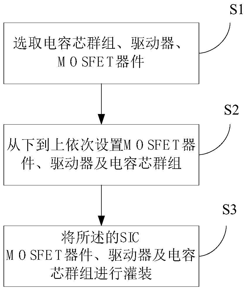
[0024] see figure 1 , an embodiment, a method for power module capacitor layout, comprising the following steps:

[0025] S1. Select the capacitor core group, the driver, and the SIC MOSFET device;

[0026] The capacitor core group includes: a positive busbar, a capacitor core, and a negative busbar. The positive busbar is arranged on the lower surface of the capacitor core and soldered to it, and the negative busbar is arranged on the upper surface of the capacit...


PUM


Abstract

The invention provides a power module capacitor layout method. The power module capacitor layout method comprises the following steps: S1, selecting a capacitor core group, a driver and an MOSFET device, wherein the MOSFET device is an SIC MOSFET device; S2, setting the MOSFET device, the driver and the capacitor core group from bottom to top in sequence, wherein a gap is formed between the capacitor core group and the driver, the capacitor core group is electrically connected with the MOSFET device and is arranged above the MOSFET device, and the driver is installed and fixed through auxiliary terminals welded to the MOSFET device; and S3, filling the SIC MOSFET device, the driver and the capacitor core group. Through the technical scheme, an epoxy resin integral filling mode is adopted,due to the fact that the structure that capacitor cores and the power device are connected in layout is optimized, the stray inductance is reduced, and the application condition of the SIC MOSFET power device with higher switching speed is met.

Description

technical field [0001] The invention relates to the field of electric vehicle controllers, in particular to a method for capacitor layout of a power module. Background technique [0002] The power module is an independent functional body that integrates the necessary components in a certain combination to meet the work of power semiconductor devices. The internal components of this module are connected by fasteners or soldered, and the external shell can be made of aluminum. The alloy casing can also be potted as a whole without using the casing. In the prior art, power modules mainly appear in megawatt-level high-power converter devices, and power semiconductor devices are mainly IGBTs, while the existing products in the electric vehicle industry are power controllers, namely power modules. In combination with a motor control unit (MCU), the semiconductor power device is also an IGBT. [0003] The layout methods in the existing automotive controllers are mainly: independe...

Claims


Application Information

Patent Timeline
Patent Type & Authority Applications(China)
IPC IPC(8): H01L25/07H01L23/367H01L23/31H01L21/56B60L53/20
CPCB60L53/20H01L21/561H01L23/3121H01L23/367H01L25/071Y02T10/70Y02T10/7072Y02T90/14
Inventor 刘斌杨光杜野马伯乐黄小华王田军
Owner SHENZHEN HOVERBIRD ELECTRONICS TECH CO LTD
Why Eureka
Try Eureka