Chlorosilane high-boiling residue recovery technology combining slurry treatment with pyrolysis reaction

A technology of cracking reaction and chlorosilane, which is applied in the direction of silicon compound, halosilane, chemical recovery, etc., can solve the problems of increased production cost, catalyst deactivation, high boiling material cracking rate cannot be improved, etc., to avoid accumulation and prolong use The effect of longevity

Active Publication Date: 2019-08-02
TIANJIN UNIVERSITY OF SCIENCE AND TECHNOLOGY
View PDF9 Cites 6 Cited by
  • Summary
  • Abstract
  • Description
  • Claims
  • Application Information

AI Technical Summary

Problems solved by technology

This method does not pretreat chlorosilane high boilers, and does not recover silicon tetrachloride in the raw materials in advance, which is one of the cracking products. Limited by the reaction balance, the cracking rate

Method used


Image

  • Chlorosilane high-boiling residue recovery technology combining slurry treatment with pyrolysis reaction
  • Chlorosilane high-boiling residue recovery technology combining slurry treatment with pyrolysis reaction
  • Chlorosilane high-boiling residue recovery technology combining slurry treatment with pyrolysis reaction

Examples


example 1

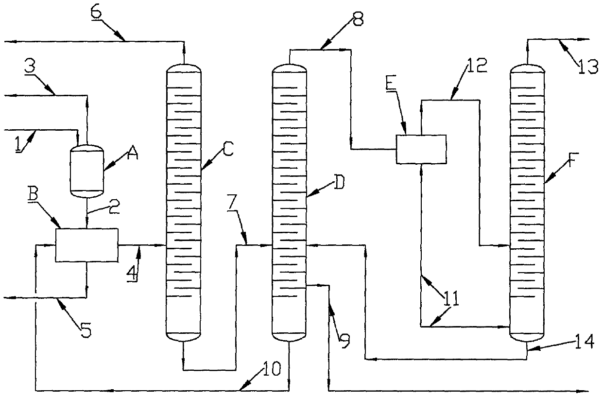
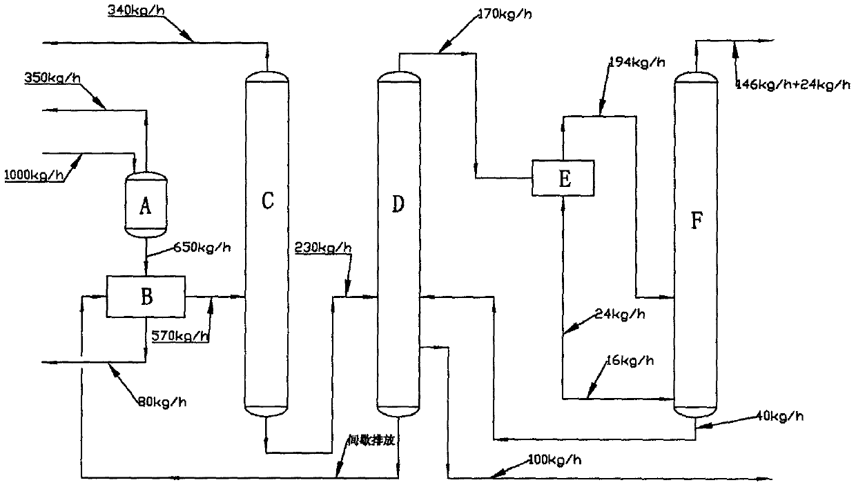
[0052] The processing capacity of chlorosilane high-boiler slurry is 1000kg / h, and the content of silicon tetrachloride is 70%. 2 Cl 6 The representative chlorosilane oligomer content is 12%, the chlorosilane high polymer content is 10%, and the solid impurity content is 8% as an example, and the calculation is explained. The specific process flow and material balance are as attached figure 2 Shown.

[0053] The 1000kg / h chlorosilane high-boiler slurry enters the silicon tetrachloride recovery equipment (A), and the amount of silicon tetrachloride recovered is 350kg / h, and the remaining 650kg / h material enters the deslagging drying equipment (B). Through the equipment (B), 80kg of solid impurities are removed per hour, and 570kg of liquid phase high boilers are obtained and sent to the silicon tetrachloride recovery tower (C) of the high boiling cracking device. The operating pressure of the tower (C) is 0.1MPa(G). Through the separation of the tower (C), the amount of silicon t...

example 2

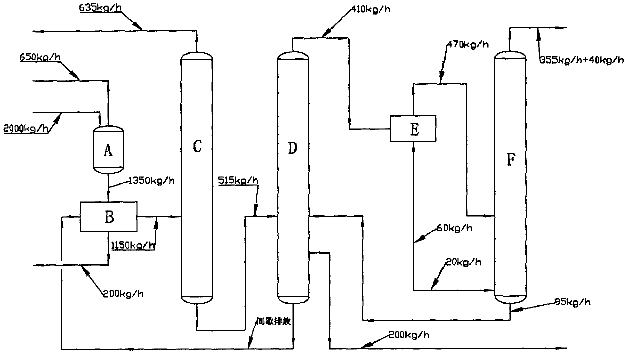
[0055] The processing capacity of chlorosilane high-boiler slurry is 2000kg / h, and the content of silicon tetrachloride is 65%. 2 Cl 6 The representative chlorosilane oligomer content is 15%, the chlorosilane high polymer content is 10%, and the solid impurity content is 10% as an example, and the calculation is explained. The specific process flow and material balance are as attached image 3 Shown.

[0056] The 2000kg / h chlorosilane high-boiler slurry enters the silicon tetrachloride recovery equipment (A) to recover 650kg / h of silicon tetrachloride, and the remaining 1350kg / h material enters the deslagging and drying equipment (B). Through equipment (B), 200kg of solid impurities are removed per hour, and 1150kg of liquid phase high boiler is sent to the silicon tetrachloride recovery tower (C) of the high boiling cracking device. The operating pressure of the tower (C) is 0.1MPa(G). Through the separation of the tower (C), the amount of silicon tetrachloride recovered from th...


PUM


Abstract

The invention relates to a chlorosilane high-boiling residue recovery technology combining slurry treatment with pyrolysis reaction. The technology comprises the following steps: pre-treating chlorosilane high-boiling residue slurry through a slurry treatment device, separating recycled materials, feeding a chlorosilane low polymer into a pyrolysis reactor loaded with a catalyst to react with hydrogen chloride to obtain a pyrolysis product, and performing subsequent separation to obtain a monosilane product. The chlorosilane high-boiling residue recovery technology combining the slurry treatment with the pyrolysis reaction has the advantages that the slurry treatment device can effectively remove solid impurities, such as metal chloride and the like, contained in the materials, and inactivation and coking phenomena of a pyrolysis catalyst are avoided; a high-boiling residue separation tower has a function of beside collection, and can separate liquid-phase high polymers, so that accumulation is avoided; a pyrolysis reaction rectifying tower performs pyrolysis reaction and separation process at the same time, so that the pyrolysis ratio can be improved.

Description

Technical field [0001] The invention relates to the field of chlorosilane production, in particular to a chlorosilane high-boiling material recovery process combining slurry treatment and cracking reaction. Background technique [0002] At present, the domestic polysilicon production process mainly adopts the modified Siemens method, and its process mainly includes: trichlorosilane preparation process, trichlorosilane refining process, trichlorosilane reduction process and reduction recovery process. Due to the constraints of the purity of silicon powder raw materials, catalysts and process conditions, a small amount of Si-C, Si-Si, Si-C-Si, Si-C-Si, Si-C, Si-Si, Si-C-Si, Si-O-Si bond compounds and high boilers composed of residual silicon powder, catalyst and metal chloride. High boiling material is a sauce-colored, pungent odor and strong corrosive mixed liquid. It is flammable, explosive and not easy to store. In addition, the market capacity is limited. If it is not processe...

Claims


Application Information

Patent Timeline
IPC IPC(8): C01B33/107
CPCC01B33/107C01B33/1071Y02P20/584
Inventor 王红星陈锦溢华超李飞
Owner TIANJIN UNIVERSITY OF SCIENCE AND TECHNOLOGY
Why Eureka
Try Eureka