Deep deacidification and white smoke removing system and method for flue gas of garbage power plant

A technology for power plants and flue gas, applied in the field of flue gas deacidification and dewhitening systems, can solve the problems of high power, difficult to achieve, and high energy consumption of the absorption liquid circulating pump, and achieves the solution of atmospheric haze pollution and reduction of moisture content. Effect

Inactive Publication Date: 2019-08-13
凤阳海泰科能源环境管理服务有限公司
View PDF9 Cites 3 Cited by
  • Summary
  • Abstract
  • Description
  • Claims
  • Application Information

AI Technical Summary

Problems solved by technology

[0002] As environmental protection requirements become more and more stringent, NOx, SOx, HCl, dust, Hg, dioxins and other pollutants in the flue gas need to be discharged up to the standard, and the white smoke at the chimney outlet needs to be treated. Waste incineration plants The traditional method is semi-dry method + dry method + flue gas de-whitening system to achieve double effects. The semi-dry method + dry method deacidification mode adopted by waste incineration plants can meet the national standard (sulfur dioxide 80mg/Nm 3 , hydrogen chloride 50mg/Nm 3 ), but for the design value of local regulations for ultra-low emissions (sulfur dioxide 10mg/Nm 3 , hydrogen chloride 5mg/Nm 3 ) is difficult to achieve
[00

Method used


Image

  • Deep deacidification and white smoke removing system and method for flue gas of garbage power plant

Examples


Embodiment Construction

[0029] The present invention will be described in further detail below in conjunction with specific examples, but not as a limitation of the present invention.

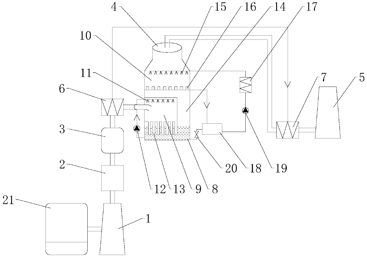
[0030] refer to figure 1 , The deep deacidification and whitening system of flue gas in a garbage power plant of the present invention includes a desuperheating tower 1, an activated carbon injector 2, a bag filter 3, a wet tower 4, and a chimney 5.

[0031] The flue gas inlet of the desuperheating tower 1 is connected to the exhaust port of the garbage incinerator 21, the flue gas outlet of the desuperheating tower 1 is connected to the activated carbon injector 2, and the flue gas outlet of the activated carbon injector 2 is connected to the bag filter 3 , the air outlet of the bag filter 3 is connected to the first heat exchanger 6, and the air outlet of the first heat exchanger 6 is connected to the wet tower 4, and the rear stage of the wet tower 4 is connected to the second heat exchanger 7, The air outlet of t...


PUM


Abstract

The invention discloses a deep deacidification and white smoke removing system and method for flue gas of a garbage power plant. The system comprises a temperature reducing tower. The flue gas is introduced into a wet tower after preliminary deacidification by means of a semi-drying method, first deacidification is completed in a spraying bin, and then the flue gas is introduced into a slurry tankfor a gas-liquid reaction to complete second deacidification so that the deacidification efficiency of the flue gas can reach 90% or above; at the same time, the flue gas is condensed and dehumidified in a dehumidifying layer to reduce the water content in the flue gas, so that the two processes including deacidification and white smoke removing are integrally completed in the wet tower; during spraying deacidification, a certain guarantee is provided for the reaction time of spraying slurry and the flue gas, the slurry is in full contact with the flue gas, the demand for the height of a tower body is not high, and the energy consumption of the system is reduced; the flue gas is introduced into the slurry tank through a descending pipe after being subjected to spraying deacidification inthe spraying bin, acid gas removal and deep dust removal are further carried out through a slurry reaction, and ultra-low emission requirements are met.

Description

technical field [0001] The invention relates to a flue gas deacidification and whitening system, in particular to a system and method for deep deacidification and whitening of flue gas from a waste power plant. Background technique [0002] As environmental protection requirements become more and more stringent, NOx, SOx, HCl, dust, Hg, dioxins and other pollutants in the flue gas need to be discharged up to the standard, and the white smoke at the chimney outlet needs to be treated. Waste incineration plants The traditional method is semi-dry method + dry method + flue gas de-whitening system to achieve double effects. The semi-dry method + dry method deacidification mode adopted by waste incineration plants can meet the national standard (sulfur dioxide 80mg / Nm 3 , hydrogen chloride 50mg / Nm 3 ), but for the design value of local regulations for ultra-low emissions (sulfur dioxide 10mg / Nm 3 , hydrogen chloride 5mg / Nm 3 ) is difficult to achieve. [0003] In addition, be...

Claims


Application Information

Patent Timeline
IPC IPC(8): B01D53/75B01D53/80B01D53/68B01D53/56B01D53/50B01D50/00B01D46/02F23J15/00F23J15/02F23J15/04F23J15/06
CPCB01D53/80B01D53/75B01D53/502B01D53/56B01D53/68B01D46/02B01D53/343F23J15/006F23J15/02F23J15/025F23J15/022F23J15/04F23J15/06B01D2258/0283B01D2251/404B01D2251/304B01D2251/604F23J2217/10F23J2215/10F23J2215/20F23J2215/30F23J2219/70B01D50/60
Inventor 何秀锦王军祥李志伟
Owner 凤阳海泰科能源环境管理服务有限公司
Why Eureka
Try Eureka