Flow chemical reaction device

A chemical reaction and strengthening device technology, applied in chemical/physical/physical chemical reactors, chemical instruments and methods, chemical/physical processes, etc., can solve problems such as high labor costs, low efficiency, and low safety, and achieve improved Productivity, shortened response time, and improved safety effects

Inactive Publication Date: 2019-09-06
PEKING UNIV SHENZHEN GRADUATE SCHOOL
View PDF12 Cites 7 Cited by
  • Summary
  • Abstract
  • Description
  • Claims
  • Application Information

AI Technical Summary

Problems solved by technology

[0007] In order to solve the technical problems of low safety, high labor cost and low efficiency in the chemical reaction of the prior art, the present invention provides a flow chemical reaction device, which is specifically realized through the following technical solutions:

Method used


Image

  • Flow chemical reaction device
  • Flow chemical reaction device
  • Flow chemical reaction device

Examples


Embodiment 1

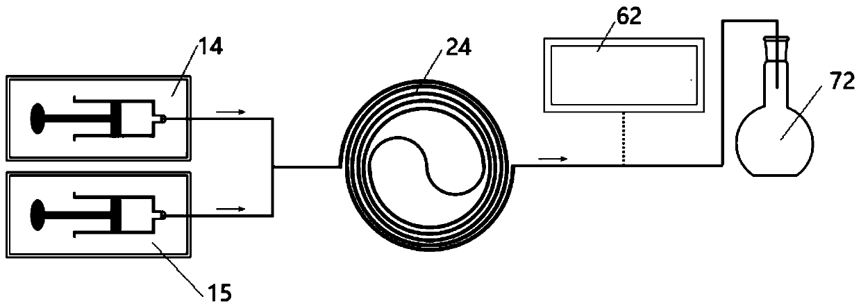
[0035] This embodiment provides a flow chemical reaction device, such as figure 1 , comprising a reactor 24, two liquid injection devices 14,15, a detection device 62 and a collection container 72, wherein the liquid injection devices 14,15 communicate with two sample inlets of the reactor 24 through pipelines, and the liquid injection devices 14,15 The output reagent solutions are mixed in the reactor 24 and sent to the chemical reaction. The sample outlet of the reactor 24 communicates with the detection device 62 and the collection container 72 through pipelines.

[0036] In this embodiment, the reactor 24 adopts a section of micropipeline coil, and the pipeline coil is made of chemically resistant polymer material, silicon dioxide or stainless steel. In this embodiment, the micropipeline coil adopts tetrafluoroethylene-perfluoroalkoxyethylene The base ether copolymer (PFA) material has good corrosion resistance. The diameter of the micropipe is 100-1000um, and the length ...

Embodiment 2

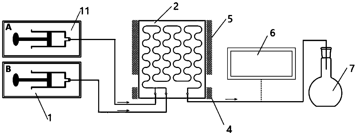
[0043] This embodiment provides a flow chemical reaction device, such as figure 2, including two syringe pumps 1, 11, a reactor, a detection device 6 and a collection container 7, the reactor in this embodiment is a microfluidic chip 2, the micropipe in the microfluidic chip 2 in this embodiment It is an S-shaped pipe, and the microfluidic chip is made of high-temperature-resistant and chemical-resistant borosilicate glass, and a continuous S-shaped pipe or a circular pipe with a scale of 100-1000um is etched in the glass chip. In this embodiment, the diameter of the S-shaped pipeline is about 200um, and the total volume of the pipeline is about 70ul. One end of the S-shaped pipeline is provided with two sample inlets, and the other end is provided with a sample outlet. The injection ports of the two syringe pumps 1 and 11 pass through the The tubing communicates with the two injection ports.

[0044] The detection device 6 is a Waters high electrospray mass spectrometer, an...

Embodiment 3

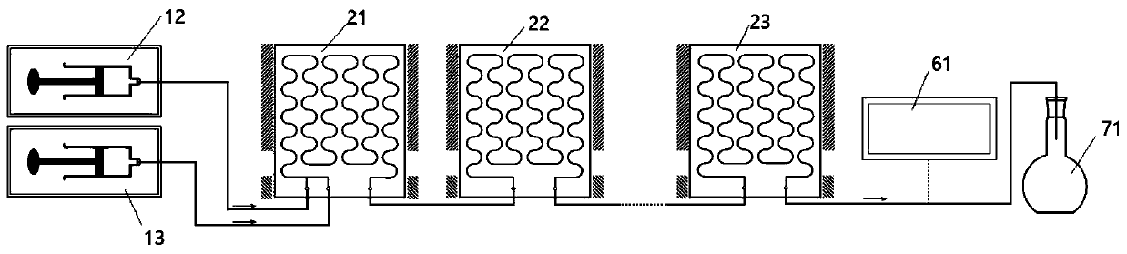
[0053] In order to increase the time for the reaction solution to be extracted and retained in the microfluidic chip, the number of microfluidic chips can be increased as required, such as image 3 , the flow chemical reaction device provided in this embodiment includes three microfluidic chips 21, 22, 23, two liquid injection pumps 12, 13, a detection device 61, and a collection container 71, wherein two liquid injection devices 12 , the liquid injection port of 13 communicates with the two sample inlets on the microfluidic chip 21 through pipelines, and the remaining two microfluidic chips 22, 23 are connected in sequence, and the detection device 61 is arranged on the downstream of the microfluidic chip 23 for The attribute of the reaction product is detected, and the collection container 71 is used to collect the detected reaction product. In this embodiment, the exterior of each microfluidic chip 21, 22, 23 is also equipped with a corresponding process intensification dev...


PUM

PropertyMeasurementUnit
Diameteraaaaaaaaaa

Abstract

The invention belongs to the technical field of organic synthesis and discloses a flow chemical reaction device. The device comprises one or more reactors, and each reactor is provided with a discharging port and two or more feeding ports; a sealed micro pipe is arranged in each reactor, and two or more feeding ports are communicated with the corresponding discharging port through the corresponding micro pipe; each feeding port is communicated with a liquid injection device through a pipe, the liquid injection devices are used for injecting samples into the reactors, the device further comprises a process reinforcement device matched with the reactors, and the process reinforcement device provides required external reaction conditions for the reactors. According to the device, the whole reaction and detection process is conducted in a sealed environment, leakage of poisonous and harmful substances is avoided, the danger of experiments with explosion risks to operators is avoided, and the safety of the chemical synthesis process is improved. In addition, a micro-fluidic chip is used as the continuous flow chemical reaction device of the reactors, continuous synthesis is achieved, manual participation is reduced, the reaction time is shortened, and the production efficiency is improved.

Description

technical field [0001] The invention belongs to the technical field of organic synthesis, and in particular relates to a flow chemical reaction device. Background technique [0002] Organic synthesis refers to the process of synthesizing organic matter from simpler compounds or simple substances through chemical reactions. Sometimes degradation of complex raw materials to simpler compounds is also included. Organic synthesis often uses reaction conditions such as heating, light, microwave and even pressure. [0003] A core content of organic synthetic chemistry is the synthesis of various organic molecules. In scientific research and development based on universities and scientific research institutes, the synthesis of natural products, drugs, and functional molecules requires a large number of organic reactions, while the traditional synthesis method uses a glass flask as a reactor synthesis method, known as For batch chemistry. The reagents required for the reaction ar...

Claims


Application Information

Patent Timeline
IPC IPC(8): B01J19/00
CPCB01J19/0093
Inventor 姜和明张欣豪吴云东
Owner PEKING UNIV SHENZHEN GRADUATE SCHOOL
Why Eureka
Try Eureka