Microfluidic sample concentration device based on photo-thermal evaporation as well as application method

A concentration device and microfluidic technology, applied in the field of microfluidics, can solve problems such as difficult gas-liquid evaporation area, low efficiency of evaporation system, and reduced evaporation efficiency, so as to increase the evaporation area, solve the problem of uncontrollable free gas-liquid interface, The effect of improving efficiency

Active Publication Date: 2019-09-06
CHONGQING UNIV
View PDF3 Cites 2 Cited by
  • Summary
  • Abstract
  • Description
  • Claims
  • Application Information

AI Technical Summary

Problems solved by technology

Furthermore, when the microfluidic chip is used to concentrate and evaporate the sample solution, it is difficult to ensure a reasonable gas-liquid evaporation area due to the small characteristic size of the microchannel, which greatly reduces the evaporation efficiency.
Finally, the overall evaporation efficiency of the microfluidic chip based on evaporative concentration needs to be improved. At present, the more common evaporative concentration device is to load the photothermal conversion medium in the microchannel, such as gold, silver and other precious metals, and control the light beam to carry out the process. The sample solution is heated by irradiation to achieve the effect of concentrated evaporation. Although the photothermal medium mentioned above has a high photothermal conversion efficiency, the efficiency of the evaporation system based on the free gas-liquid interface in the microchannel is still low, and it still has a lot of advantages. big room for improvement

Method used


Image

  • Microfluidic sample concentration device based on photo-thermal evaporation as well as application method
  • Microfluidic sample concentration device based on photo-thermal evaporation as well as application method

Examples


Embodiment 1

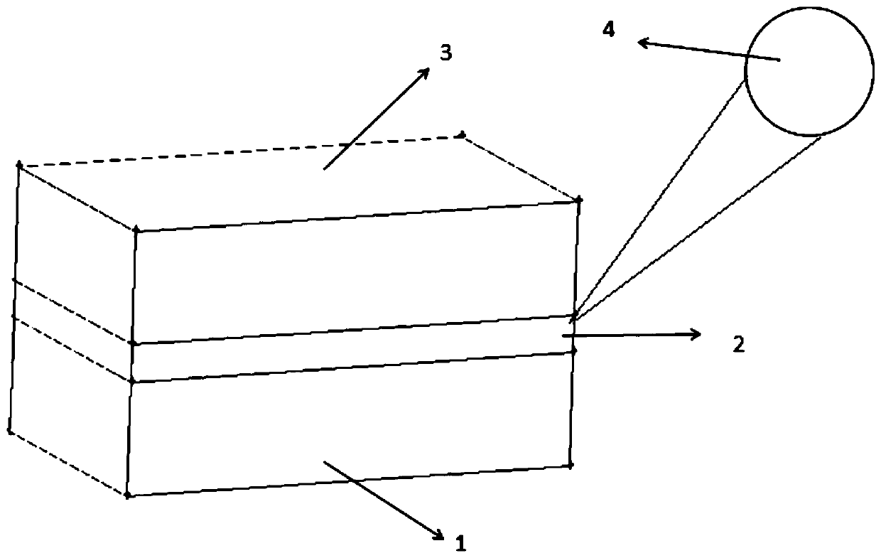
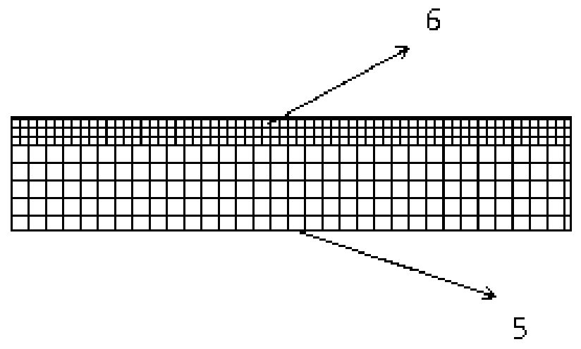
[0022] Example 1: see figure 1 with figure 2, a microfluidic sample concentration device based on photothermal evaporation, comprising a sample solution channel 1, that is, a substrate, a porous photothermal evaporation layer 2 is arranged above the sample solution channel 1, and a porous photothermal evaporation layer 2 is arranged above the porous photothermal evaporation layer 2 A carrier gas channel 3 is provided, and a light source 4 is provided on the outside of the porous photothermal evaporation layer 2; the porous photothermal evaporation layer 2 is composed of a hydrophilic porous photothermal medium layer 5 and a hydrophobic gas diffusion layer 6; the hydrophilic The water porous photothermal medium layer 5 generates capillary suction force on the liquid, so that the sample solution enters the hydrophilic porous photothermal medium layer 5. At the same time, the hydrophilic porous photothermal medium layer 5 absorbs the incident light of the light source 4 to gener...

Embodiment 2

[0028] Embodiment 2. The method of using a microfluidic sample concentration device based on photothermal evaporation, the concentration device includes a sample solution channel 1, a porous photothermal evaporation layer 2 is arranged above the sample solution channel 1, and the porous photothermal evaporation layer 2 is arranged above the sample solution channel 1. A carrier gas channel 3 is arranged above the evaporation layer 2, and a light source 4 is arranged outside the porous photothermal evaporation layer 2; the porous photothermal evaporation layer 2 is composed of a hydrophilic porous photothermal medium layer 5 and a hydrophobic gas diffusion layer 6 Composition; the hydrophobic gas diffusion layer 6 is a hydrophobic structure, located on the upper part of the hydrophilic porous photothermal medium layer 5; the carrier gas channel 3 has a gas microchannel structure, and the inlet of the gas microchannel is connected to the outlet of the purge gas storage device The ...

Embodiment 3

[0033] Embodiment 3: A microfluidic sample concentration device based on photothermal evaporation can be prepared as follows:

[0034] A. Processing of sample solution channel 1 and carrier gas channel 3: select two pieces of polydimethylsiloxane, rubber or resin elastic materials with the same shape and size as the matrix of sample solution channel 1 and carrier gas channel 3 respectively, through The soft lithography technique processes solution channels and gas microchannels on the substrate, respectively.

[0035] B, the making of porous photothermal evaporation layer 2:

[0036] B1. Evenly mix liquid phenol, calcium lignosulfonate, and sodium hydroxide at a mass ratio of 39.2:4.4:1, heat at a constant temperature of 80°C for 30 minutes, and then add 30% based on the mass ratio of 1:1.27 based on the mass of the mixture Formaldehyde aqueous solution was vacuum dehydrated at a temperature of 50° C. and a pressure of 0.1 MPa for 30 minutes to obtain a water-based phenolic r...


PUM


Abstract

The invention discloses a microfluidic sample concentration device based on photo-thermal evaporation as well as an application method. The microfluidic sample concentration device based on the photo-thermal evaporation comprises a sample solution channel and is characterized in that a porous photo-thermal evaporation layer is arranged above the sample solution channel, a carrier gas channel is arranged above the porous photo-thermal evaporation layer, and a light source is arranged outside the porous photo-thermal evaporation layer; the porous photo-thermal evaporation layer is composed of ahydrophilic porous photo-thermal medium layer and a hydrophobic gas diffusion layer; the hydrophilic porous photo-thermal medium layer produces a capillary suction force on liquid, so that sample solution enters the hydrophilic porous photo-thermal medium layer, meanwhile, the hydrophilic porous photo-thermal medium layer absorbs incident light of the light source and produces photothermal effect,so that the sample solution absorbs heat and is evaporated to produce gas, and then evaporation and concentration on the sample solution are realized; and the hydrophobic gas diffusion layer is of ahydrophobic structure and is located at the upper part of the hydrophilic porous photo-thermal medium layer. The microfluidic sample concentration device disclosed by the invention can be widely applied to the fields of crystal purification, drug synthesis and food engineering.

Description

technical field [0001] The invention relates to the field of microfluidics, in particular to a microfluidic sample concentration device based on photothermal evaporation and a method for using it. Background technique [0002] Microfluidic chips were developed in the field of analytical chemistry in the 1990s, and are playing an increasingly important role as analytical systems, biomedical devices, and chemical and biochemical tools. With its large specific surface area and extremely low sample demand, the microfluidic chip achieves extremely high analysis efficiency. Many microfluidic chips can be processed within a few seconds to tens of seconds, which is much lower than that of conventional laboratories. The required amount of sample is used to complete determination, separation or other more complex operations, which is difficult to achieve by other conventional analysis and detection methods. In addition, compared with traditional analysis and detection methods, microf...

Claims


Application Information

Patent Timeline
IPC IPC(8): G01N1/40B01L3/00
CPCB01L3/5027B01L3/502707G01N1/4022G01N2001/4027
Inventor 何雪丰谭颜斯阳陈蓉朱恂廖强叶丁丁张彪
Owner CHONGQING UNIV
Why Eureka
Try Eureka