A constant temperature and constant pressure thermal battery electrical performance testing system and testing method thereof

An electrical performance testing, constant temperature and constant voltage technology, applied in primary battery use/maintenance, testing equipment, anti-corrosion/storage batteries, etc., can solve the problems of long mold replacement cycle, long activation time, test result deviation, etc., to improve the test Efficiency, easy disassembly and cleaning, improved consistency

Inactive Publication Date: 2021-11-23
INST OF ELECTRONICS ENG CHINA ACAD OF ENG PHYSICS
View PDF5 Cites 0 Cited by
  • Summary
  • Abstract
  • Description
  • Claims
  • Application Information

AI Technical Summary

Problems solved by technology

At present, there are two main ways to heat a single thermal battery. One is to pressurize and heat the upper and lower furnace plates. This method directly contacts the battery conductive fixture and applies pressure. It has the advantages of fast activation of the single thermal battery and high test efficiency. However, the pressure of the test equipment is uncontrollable. At the same time, some equipment is used directly in the air, and the influence of oxygen on the test results cannot be ruled out, and the test results will produce certain deviations; another method is the furnace body (tube furnace, high temperature furnace) Heating, first put the battery in the test mold, and then heat it in the furnace body. The advantage of this test method is that it can be protected by inert gas to avoid oxidation of the electrode material, but the pressure of this test method cannot be adjusted, and the activation time is longer , the replacement mold cycle is long, and the test efficiency is low. In addition, if the tube furnace is not placed in a dry room (controlled humidity) for this test method, the water vapor in the air will mix with the battery negative electrode material LiSi or LiSi during the assembly process. LiB reacts and affects test results

Method used


Image

  • A constant temperature and constant pressure thermal battery electrical performance testing system and testing method thereof
  • A constant temperature and constant pressure thermal battery electrical performance testing system and testing method thereof

Examples


Embodiment

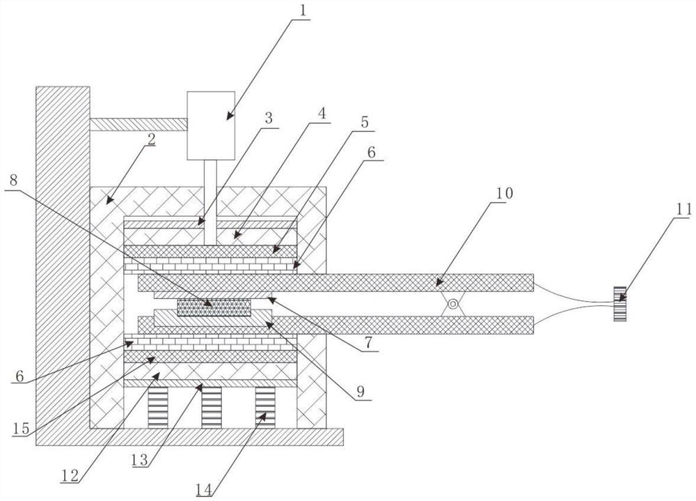
[0034] like figure 1 As shown, the constant temperature and constant pressure thermal battery electrical performance testing system includes an electrical performance testing system and a test device arranged in a glove box. The electrical performance testing system is preferably an Arbin BT-ML discharge device, and its voltage range is 0V- 40V, voltage test accuracy is + / -0.05% FSR (full scale); current range is 0A-30A, current test accuracy is + / -0.05% FSR (full scale).

[0035] like figure 1 As shown, the test device includes a holding furnace body 2, and a constant temperature and constant pressure system is arranged in the holding furnace body 2. Press machine 1, preferably press machine 1 is an electric press machine.

[0036] like figure 1 As shown, the constant temperature and constant pressure system includes a first heating hob 5 and a second heating hob 15 arranged in the holding furnace body 2 with a gap, wherein the first heating hob 5 is slidably arranged on t...


PUM


Abstract

The invention discloses a constant temperature and constant pressure thermal battery electrical performance testing system and a testing method thereof. The test system includes an electrical performance test system and a test device arranged in a glove box; the test device includes a matched constant temperature and pressure system and a thermal battery assembly system; the constant temperature and pressure system includes a first heating furnace with a gap and a second Heating hob; the first heating hob is connected to the press, and a thermal battery assembly system is arranged between the first heating hob and the second heating hob; the thermal battery assembly system includes Between the hob and the conductive fixture of the electrical performance testing system; a thermal battery is arranged in the conductive fixture. The single thermal battery discharge system and test method of the present invention overcome many shortcomings of the existing single thermal battery discharge test system, can quickly activate the thermal battery, have relatively ideal single thermal battery discharge conditions, and can greatly improve Consistency of single cell thermal battery discharge.

Description

technical field [0001] The invention belongs to the technical field of thermal batteries, and in particular relates to a constant temperature and constant pressure type thermal battery electric performance testing system and a testing method thereof. Background technique [0002] Thermal battery is a kind of chemical power source. It is a primary battery activated by heating. Its electrolyte is molten salt, which is solid at room temperature and non-conductive. When in use, the molten salt is melted into an ion conductor by heating, and the battery is activated to start discharging. Since the electrolyte of the thermal battery is solid at normal temperature, there is almost no self-discharge phenomenon, and the thermal battery has a long storage time, which can reach 20 years. The molten electrolyte has high conductivity, so hot batteries can be discharged at high current densities. Thermal batteries are widely used in weaponry due to their high reliability, long storage li...

Claims


Application Information

Patent Timeline
Patent Type & Authority Patents(China)
IPC IPC(8): H01M6/50G01R31/387
CPCG01R31/387H01M6/5038H01M6/5072H01M6/5083
Inventor 杨兆堂闫军刘效疆
Owner INST OF ELECTRONICS ENG CHINA ACAD OF ENG PHYSICS
Why Eureka
Try Eureka