The method of controlling friction and wear often comes from the characterization of the test. With the development of
tribology, the working conditions of the test research are becoming more and more complex. The existing one-way speed point
contact test bench can no longer meet the needs of the test. For example:
Chinese patent 201010198089.9 The heavy-duty photoelasto-hydrodynamic
oil film measurement device is composed of three parts: 1. Motion mechanism, including servo motor,
pulley, lead screw, slider and transparent material, wherein the servo motor is the power source, and the wire is driven by the
pulley The screw is fixed on the slider, and the slider is driven by the screw to slide linearly on the guide rail. The slider is equipped with a transparent material, and its lower surface is pressed on the tested piece, forming a pair of contact with the tested piece. Body, the exposed width of the transparent material is slightly greater than the length of the roller; 2. The supporting mechanism includes a pair of fixed rollers and a pair of floating rollers. The tested piece is supported by a pair of floating rollers, and the pair of floating rollers , It is also supported by the above pair of fixed rollers and loading rollers. The fixed rollers and the loading rollers are respectively equipped with rolling bearings, which can realize pure rolling; 3. The loading mechanism, including the load weight and the loading roller at the other end, the load weight After the code is amplified by the lever mechanism, it is acted on the test piece by the loading roller, and the rolling bearing is installed on the loading roller; the incident cold
light source passes through the narrow-band filter, irradiates the test piece through the
microscope, and the interference image is also magnified by the microscope and transmitted by the CCD. to
computer processing;
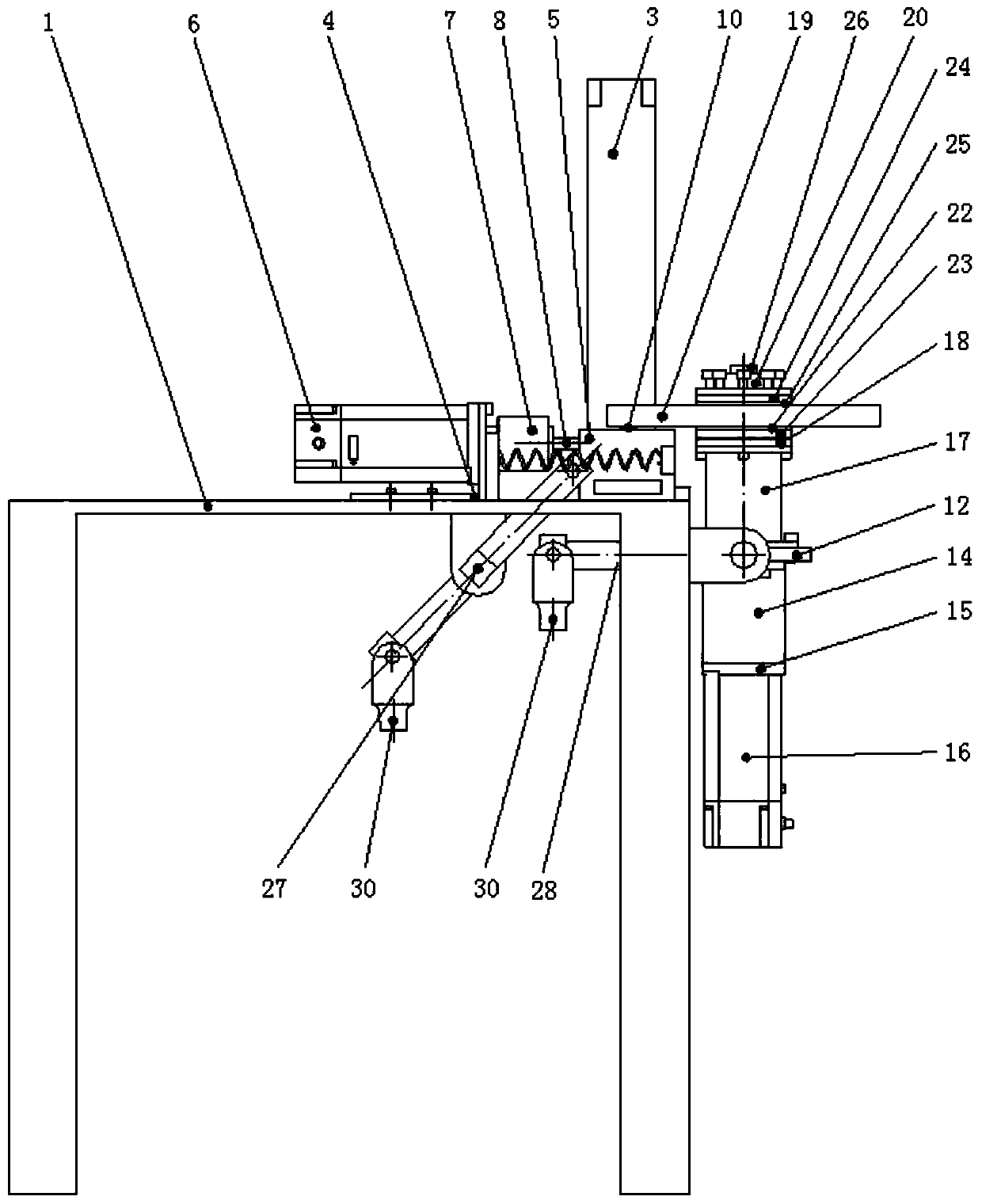
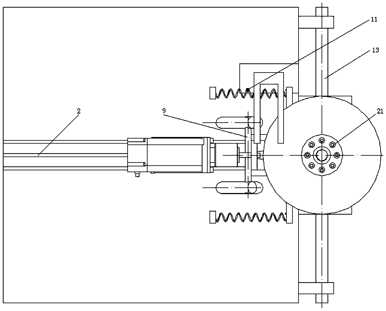
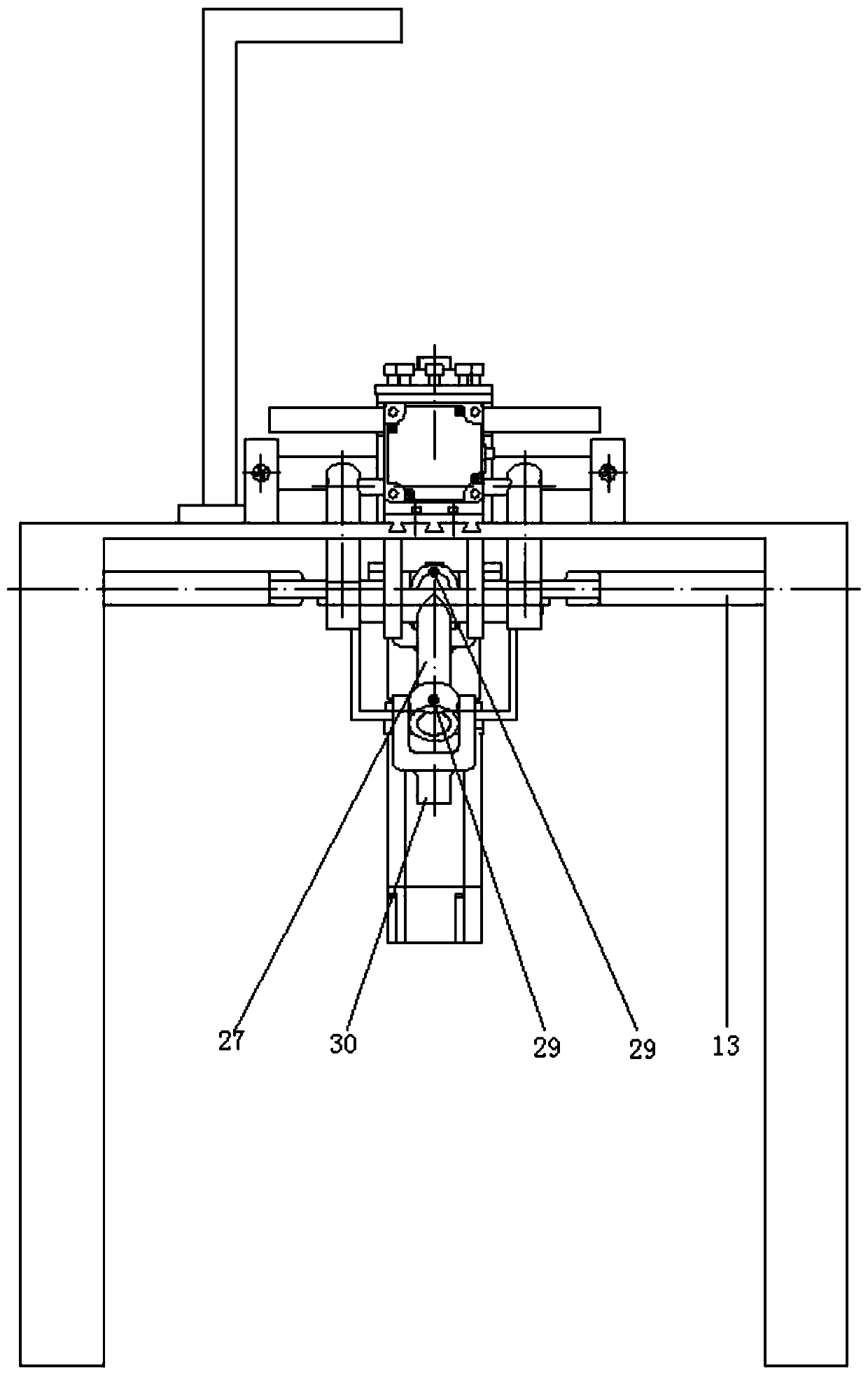
Chinese patent 201610850701.3 discloses a high-speed heavy-duty roller photoelastohydrodynamic oil film
measurement device including a motion mechanism, a loading mechanism, a support device and an
image acquisition and
processing system, and the motion mechanism includes a speed-regulating motor, a first shaft
coupling gear, speed
reducer, second
coupling, rotating disk,
bushing and transparent material, the speed regulating motor is connected with the speed
reducer through the first
coupling, and the speed
reducer is connected with the speed reducer through the second coupling The shaft device is connected with the rotating disk, the rotating disk is connected with the sleeve, the transparent material has a protruding end and an
insertion end corresponding to the protruding end, and the
insertion end is inserted into the shaft In the sleeve, the protruding end is exposed to the shaft sleeve, the rotating disk drives the shaft sleeve, and the shaft sleeve drives the transparent material to rotate, and the loading mechanism includes a movable support, a lever, and a cylinder , a
pressure sensor, a floating roller, a measured roller and a cylinder
control system, the cylinder
control system is electrically connected to the cylinder, one end of the lever is connected to the floating roller, the other end is connected to the cylinder, and the lever The middle part of the center is covered with the movable support, the floating roller contacts the measured roller, the measured roller is arranged below the floating roller, the supporting device includes an even number of supporting wheels, the An even number of supporting wheels is symmetrically distributed on both sides of the protruding end of the transparent material. The
image acquisition and
processing system includes an
image acquisition device and an
image processing system. The image acquisition device is arranged on the outside of the transparent material. The acquisition device is aligned with the tested roller, and the image acquisition device is electrically connected to the
image processing system; a circular photoelastodynamic oil film
measurement testing machine disclosed in
Chinese patent 201811155691.7 includes a base and a Bearing seat, the base is provided with a driving mechanism, a loading mechanism, and an image acquisition and
processing system. The driving mechanism includes a transmission spindle supported by the bearing seat, a sleeve is connected to the front end of the transmission spindle, and a glass ring is fixedly connected to the inner ring of the sleeve. , the roller to be tested is placed at the bottom of the inner ring of the glass ring; the loading mechanism includes a front lever set parallel to the axis of the transmission spindle, a rear lever perpendicular to the front lever and not on the same plane as the front lever, and a floating roller mounted on the front end of the front lever. Loading head, the floating roller presses vertically on the tested roller to form an oil film contact area, the front end of the rear lever exerts pressure on the rear end of the front lever, and a pressurized weight is hung on the rear end of the rear lever; image acquisition and processing system: includes
Microscope,
light source and computer for
data acquisition and processing, the microscope has a high-speed camera that captures the oil film interference pattern formed in the oil film contact area and transmits it to the computer

