
Method for gradient separation of titanium copper and titanium silicon from titaniferous slag through liquid copper cathode electrolysis

A technology for cathodic electrolysis and titanium slag, which is applied in the field of liquid copper cathode electrolysis of titanium-containing slag to separate titanium copper and titanium silicon by steps, can solve the problems of energy consumption, high cost, low titanium content, poor electronic conductivity, etc. The effect of electrolysis process safety

Inactive Publication Date: 2019-09-27
UNIV OF SCI & TECH BEIJING
View PDF5 Cites 2 Cited by
  • Summary
  • Abstract
  • Description
  • Claims
  • Application Information

AI Technical Summary

Problems solved by technology

In this method, titanium oxide is used as the anode, the electronic conductivity is poor, and the efficiency is low, and after two electrolysis, the energy consumption and cost are high
[0004] Patent CN201611033596.0 discloses a method for electrolytically extracting titanium from titanium-containing slag. The electrolysis uses liquid iron or iron alloy as the cathode, graphite as the anode, and titanium-containing slag as the electrolyte for DC electrolysis. However, due to the titanium-containing slag The presence of silicon dioxide in the medium will make silicon preferentially enter the iron, and obtain a titanium alloy with a very low titanium content, and only one type of alloy can be produced, and the efficiency is low

Method used


Image

  • Method for gradient separation of titanium copper and titanium silicon from titaniferous slag through liquid copper cathode electrolysis

Examples


Embodiment 1

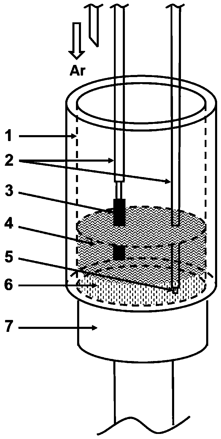
[0025] Step 1: Select a silicon nitride crucible for electrolysis, place copper powder with a purity of 99.9% at the bottom of the crucible, and use it as a cathode; place titanium-containing slag (26.46wt% CaO, 15.35wt% Al 2 o 3 , 9.40wt% MgO, 26.76wt% SiO 2 and 22.03 wt% TiO 2 ), use it as the electrolyte, choose graphite as the anode, and connect it with the conductive rod. A tungsten rod with a diameter of 4mm and a length of 1000mm is selected as the conductive rod, and is wrapped with a silicon nitride protective sleeve.

[0026] Step 2: Place the silicon nitride crucible with copper powder cathode and titanium slag in the high temperature furnace, and install the anode and conductive rod. Pass high-purity argon for protection, and raise the furnace temperature to 1500°C. When the furnace temperature reaches 1500°C, keep it warm for 2 hours, lower the cathode conductive rod to 0.2 cm from the bottom of the crucible, and lower the graphite anode to immerse in the oxid...

Embodiment 2

[0029] Step 1: Select a zirconia crucible for electrolysis, place a copper block with a purity of 99% at the bottom of the crucible, and use it as a cathode; place a titanium-containing slag (38.09wt% CaO, 25.55wt% Al 2 o 3 , 15.69wt% MgO, 8.00wt% SiO 2 and 12.67wt% TiO 2 ), use it as the electrolyte, choose Cr-Fe alloy as the anode, and connect it with the conductive rod. A tungsten rod with a diameter of 3 mm and a length of 1100 mm is selected as the conductive rod, and is wrapped with a silicon nitride protective sleeve.

[0030] Step 2: Place the zirconia crucible with copper block cathode and titanium slag in the high temperature furnace, and install the anode and conductive rod. Common argon is used for protection, and the furnace temperature is raised to 1550°C. When the furnace temperature reaches 1550°C, keep it warm for 1 hour, lower the cathode conductive rod to a distance of 0.1 cm from the bottom of the crucible, and lower the graphite anode to immerse in the...

Embodiment 3

[0033] Step 1: Select a zirconia crucible for electrolysis, place copper powder with a purity of 99.9% at the bottom of the crucible as the cathode; place titanium-containing slag (17.23wt% CaO, 23.68wt% Al 2 o 3 , 4.70wt% MgO, 10.38wt% SiO 2 ,14.01wt% TiO 2 and 30.00wt% CaF 2 ), use it as the electrolyte, choose Cr-Fe alloy as the anode, and connect it with the conductive rod. A molybdenum rod with a diameter of 3mm and a length of 1000mm is selected as the conductive rod and wrapped with a zirconia protective sleeve.

[0034]Step 2: Place the zirconia crucible with copper powder cathode and titanium-containing slag in the high-temperature furnace, and install the anode and conductive rod. Pass high-purity argon for protection, and raise the furnace temperature to 1400°C. When the furnace temperature reaches 1400°C, keep it warm for 2 hours, lower the cathode conductive rod to a distance of 0.2 cm from the bottom of the crucible, and lower the graphite anode to immerse i...


PUM

PropertyMeasurementUnit
Diameteraaaaaaaaaa
Lengthaaaaaaaaaa
Diameteraaaaaaaaaa

Abstract

The invention discloses a method for gradient separation of titanium copper and titanium silicon from titaniferous slag through liquid copper cathode electrolysis, and belongs to the field of electrochemical metallurgy. The method comprises the following steps of placing copper powder or copper blocks at the bottom of a crucible to serve as a cathode, and placing the titaniferous slag above the copper powder or the copper blocks to serve as an electrolyte, wherein an inert electrode or a graphite electrode serves as an anode; using high-melting-point metals such as molybdenum and tungsten as a conductive rod, and using silicon nitride, zirconium oxide and other materials as protective sleeves for wrapping; placing the crucible filled with the cathode and the electrolyte in a high-temperature furnace, and installing the anode and the conductive rod; and raising the furnace temperature to be 20 DEG C-100 DEG C higher than the melting point of the titaniferous slag, keeping the temperature for 0.5 h-2 h, lowering a cathode conductive rod and the anode, and carrying out direct current electrolysis. When the titanium ion activity in the titaniferous slag is 10%-60%, titanium-copper alloy can be obtained through direct current electrolysis; when the titanium ion activity in the titaniferous slag is 1%-10%, titanium-silicon alloy can be obtained through direct current electrolysis; and when the titanium ion activity in the titanium-containing slag is less than 1%, the electrolysis is stopped. According to the method disclosed by the invention, metallurgical secondary resources are comprehensively recycled through utilizing an electrochemical metallurgy method; and meanwhile, the operation is simple and the cost is low.

Description

technical field [0001] The invention relates to a method for stepwise separation of titanium-copper and titanium-silicon by liquid copper cathode electrolysis of titanium-containing slag, which belongs to the field of secondary comprehensive utilization of metallurgical resources and electrochemical metallurgy. Background technique [0002] The total amount of titanium resources in my country is 965 million tons, ranking first in the world, accounting for 38.85% of the world's proven reserves. However, most titanium resources exist in the form of composite ores such as ilmenite and vanadium-titanium magnetite, and anatase and rutile in the form of titanium dioxide only account for about 8%. The ilmenite and vanadium-titanium magnetite will be sent to iron smelting, and the titanium element will be enriched in the slag. The titanium dioxide content in these titanium-containing slags is more than 20%, and direct disposal will cause environmental pollution and waste of resource...

Claims


Application Information

Patent Timeline
IPC IPC(8): C25C3/36
CPCC25C3/36
Inventor 焦树强蒲正浩王明涌焦汉东
Owner UNIV OF SCI & TECH BEIJING
Learn More