Inductance-variable wireless intraocular pressure monitoring sensor based on microfiber pipe

A monitoring sensor and resonant sensor technology, applied in the field of medical devices, can solve the problems of clinical promotion limitations, small inductance changes, large elastic modulus of copper foil, etc., and achieve high wearing comfort, large dynamic range, and good stability Effect

Inactive Publication Date: 2019-10-01
HUAZHONG UNIV OF SCI & TECH
View PDF6 Cites 2 Cited by
  • Summary
  • Abstract
  • Description
  • Claims
  • Application Information

AI Technical Summary

Problems solved by technology

However, further studies have shown that 1) the wearing comfort is poor; 2) the sensitivity and detection accuracy of the sensor are not enough; 3) the output signal is unstable, which limits its clinical promotion
A variable inductance 24-hour intraocular pressure monitor developed in Hong Kong (see "Soft wearablecontact lens sensor for continuous intraocular pressure monitoring", Guo-ZhenChen, Ion-Seng Chan, Leo K.K.Leung, David C.C.Lam. The Hong Kong University of Science and Technology, Hong Kong.) realizes the 24-hour measurement of intraocular pressure based on the principle of inductance change, but because it uses metal copper foil as the inductance coil material, because the mechanical scale of copper foil is much larger than that of contact lens materials and human eye materials, As a result: 1) It is very difficult to couple the sensing unit into the contact lens; 2) Due to the extremely large elastic modulus of the copper foil, the diameter change of the inductance coil caused by intraocular pressure fluctuations is very small, and the inductance change is small, resulting in extremely low sensitivity of the sensor; 3) Hard copper foil leads to very poor wearing comfort of the sensor, which will affect the deformation of the cornea in the wearing area due to changes in the eye

Method used


Image

  • Inductance-variable wireless intraocular pressure monitoring sensor based on microfiber pipe
  • Inductance-variable wireless intraocular pressure monitoring sensor based on microfiber pipe
  • Inductance-variable wireless intraocular pressure monitoring sensor based on microfiber pipe

Examples


Embodiment Construction

[0027]In order to make the object, technical solution and advantages of the present invention clearer, the present invention will be further described in detail below in conjunction with the accompanying drawings and embodiments. It should be understood that the specific embodiments described here are only used to explain the present invention, not to limit the present invention. In addition, the technical features involved in the various embodiments of the present invention described below can be combined with each other as long as they do not constitute a conflict with each other.

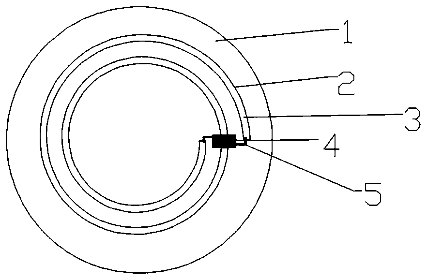
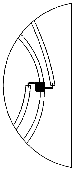
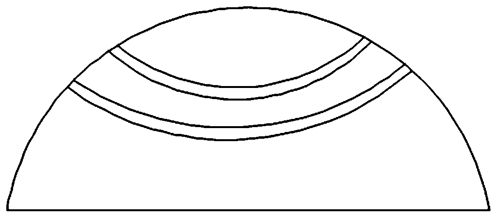
[0028] figure 2 is a side view of the structure of the intraocular pressure monitoring sensor according to the present invention, image 3 It is a front view of the structure of the intraocular pressure monitoring sensor according to the present invention. Such as figure 2 and image 3 As shown, the intraocular pressure monitoring sensor mainly includes components such as a soft contact len...


PUM


Abstract

The invention belongs to the technical field of medical apparatuses and instruments and discloses a inductance-variable wireless intraocular pressure monitoring sensor based on a microfiber pipe. Thesensor comprises a corneal contact lens (1), the microfiber pipe (2), liquid metal (3) and a patch capacitor (4), wherein the microfiber pipe and the liquid metal integrally form an inductor and are coupled with the patch capacitor to form an LC resonant sensor; the inductance value of the inductor is influenced by intraocular pressure, so that the resonance frequency of the LC resonant sensor isalso influenced by the intraocular pressure; real-time sensing monitoring of the intraocular pressure can be realized by reading the change of resonance frequency. By combining the characteristics ofclinical application of intraocular pressure monitoring and adopting the LC sensor formed by the microfiber pipe and the capacitor which are filled with the liquid metal, the intraocular pressure is monitored, and a specific structure and specific setting mode of the LC sensor are designed; the intraocular pressure can be monitored by reading the change of the resonant frequency of the LC sensor.

Description

technical field [0001] The invention belongs to the technical field of medical devices, and more specifically relates to a microfiber tube-based variable inductance wireless intraocular pressure monitoring sensor. Background technique [0002] Glaucoma is the world's first irreversible blinding eye disease. Medical practice has found that elevated intraocular pressure is not the only risk factor for glaucoma damage. Pathological intraocular pressure fluctuations also play an important role in the development of glaucoma, and its manifestations are more hidden. Therefore, it is more important to pay attention to the 24-hour fluctuation of intraocular pressure than to only pay attention to the absolute value of intraocular pressure. This view has become the consensus of glaucoma experts all over the world. [0003] The current clinical method for monitoring 24-hour intraocular pressure fluctuations is usually measured every 2 hours, but this way of replacing the whole process...

Claims


Application Information

Patent Timeline
Patent Type & Authority Applications(China)
IPC IPC(8): A61B3/16
CPCA61B3/16
Inventor 陈良洲安宏彬王祥阳戴江
Owner HUAZHONG UNIV OF SCI & TECH
Why Eureka
Try Eureka