A convenient and small near-surface atmospheric boundary layer wind tunnel and its application in population risk exposure assessment
An atmospheric boundary layer, near-ground technology, used in aerodynamic testing, testing of machine/structural components, instruments, etc., to achieve high resolution, high accuracy, and saving building space
- Summary
- Abstract
- Description
- Claims
- Application Information
AI Technical Summary
Problems solved by technology
Method used
Image
Examples
Embodiment 1
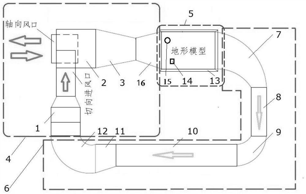
[0030] figure 1 It is a top view of the convenient and small near-surface atmospheric boundary layer wind tunnel structure of the present invention. Among them, the pipeline fan 1, the swirl air mixing pipe 2, the diffuser 3, the natural wind injection device 4, the simulation test device 5, the backflow stabilization device 6, the first elbow pipe 7, the induced air pipe 8, the second bend Head pipe 9, return air pipe 10, reducing pipe 11, third elbow pipe 12, exhaust box 13, sampling hole 14, sampling hole 15, cyclone distribution pipe 16, is the air flow direction.
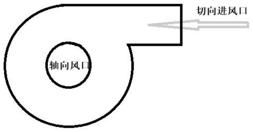
[0031] The near-ground atmospheric boundary layer wind tunnel of the present invention comprises a wind tunnel main body and a backflow stabilization device 6; the wind tunnel main body is provided with a natural wind injection device 4 and a simulation test device 5, and the natural wind injection device 4 and the simulation test device 5 and backflow stabilizing device 6 are connected in sequence; the natu...
Embodiment 2
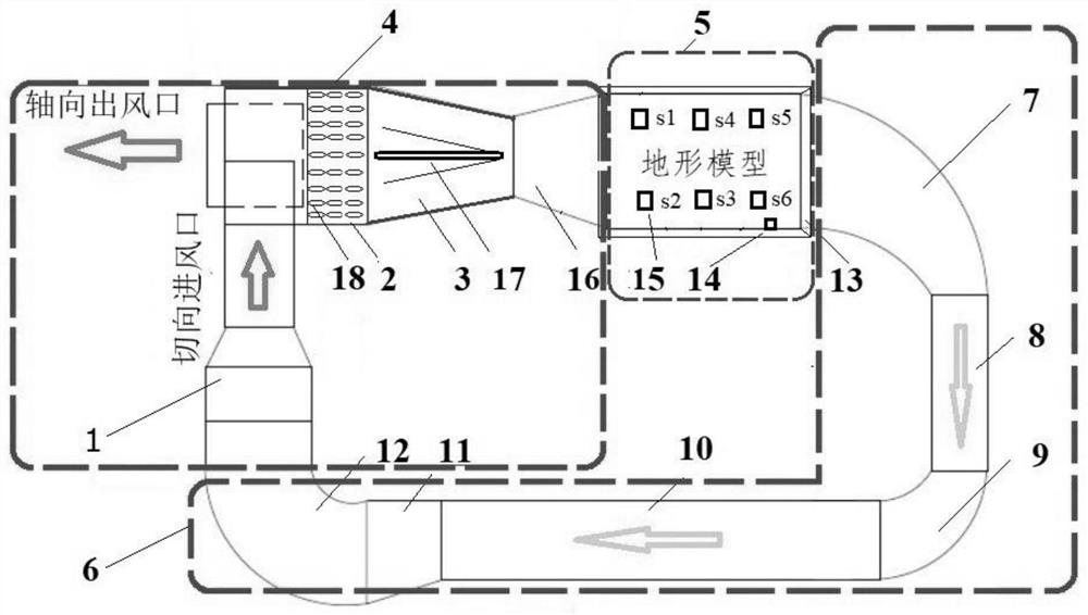
[0042] A convenient and small near-surface atmospheric boundary layer wind tunnel, such as image 3 shown, with figure 1 In addition to the same structure as described above, an inner member 17 that prevents flow separation is provided in the diffuser 3; The central position in the diffuser 3 is to ensure that the air intake conditions of the simulated test device are consistent; the swirl air mixing pipe 2 is provided with multiple groups of static mixing spiral rods 18, and the static mixing spiral rods 18 are spiral The strips are bundled and welded on the inner wall surface of the swirling air mixing pipe 2, so that the concentration, speed and flow pattern of the pseudo-natural wind can be uniform and stable. According to the wind speed simulation results of the inlet pipe in the wind tunnel test section, the natural wind field of the wind tunnel is measured at a wind speed of 1.5m / s after the wind speed stability evaluation. The data collection points are distributed at...
Embodiment 3
[0045] based on Figure 5 As shown in the wind tunnel structure, the data collection points are distributed at points s4, s5 and s6 of the sampling hole 15. The humidity of the experimental test is set to 90% RH, the wind speed is 3.3m / s, and the wind direction is N. In the terrain model, the data The collection point s4 is the center, and calabash moss is arranged in a circular area with a diameter of 0.1m around it. There is a sampling hole in the terrain model in the wind tunnel, and the sampling hole 14 is located in the industrial area of the terrain model, the hole shape is circular, and the hole cross-sectional area is 0.1m 2 , the inlet velocity of the injection hole is 0.5m / s, and the injection component is 300μg / m 3 Xylene-atmospheric mixed gas. The wind tunnel diffusion flow equalization device is provided with an umbrella-shaped internal member 17, and a static mixing spiral rod 18 made of silicon carbide is installed in the swirling air mixing pipe. The mass ...
PUM
 Abstract
Description
Claims
Application Information
 - R&D
- Intellectual Property
- Life Sciences
- Materials
- Tech Scout
- Unparalleled Data Quality
- Higher Quality Content
- 60% Fewer Hallucinations
Browse by: Latest US Patents, China's latest patents, Technical Efficacy Thesaurus, Application Domain, Technology Topic, Popular Technical Reports.
© 2025 PatSnap. All rights reserved.Legal|Privacy policy|Modern Slavery Act Transparency Statement|Sitemap|About US| Contact US: help@patsnap.com


