Check patentability & draft patents in minutes with Patsnap Eureka AI!

Low-power-consumption high-speed current comparator circuit

A current comparator, high-speed technology, applied in multiple input and output pulse circuits, electrical components, generating electric pulses, etc., can solve the problems of large temperature drift, small signal working dead zone, large power consumption, etc., to achieve The effect of reducing delay, saving power consumption and reducing deviation

Active Publication Date: 2019-10-15
UNIV OF ELECTRONIC SCI & TECH OF CHINA
View PDF6 Cites 11 Cited by
  • Summary
  • Abstract
  • Description
  • Claims
  • Application Information

AI Technical Summary

Problems solved by technology

[0003] Traff H.Novel approach to high speed CMOS current comparators[J].Electronics Letters,1992, 28(3):310-312. A current comparator based on source-following stage is proposed. The advantage of this structure is the delay time Short and relatively high precision, but the structure has a dead zone when working with small signals within the dynamic range of the input voltage, which is a serious disadvantage
In order to improve this problem, Banks D.ToumazouC.Low-power high-speed current comparator design [J].Electronics Letters,2008,44(3):171-172. In the paper, it is proposed that the input stage adopts multi-stage cascading. Constitutes a current comparator, but this structure has a large drift with temperature and consumes a lot of power
There is also a current comparator usually composed of a differential structure, which is commonly used in a differential amplifier. The differential amplifier can suppress common-mode noise and improve the signal processing accuracy of the circuit, but this circuit increases the complexity of the circuit and increases the chip area and cost, usually the structure is suitable for parallel ADC

Method used


Image

  • Low-power-consumption high-speed current comparator circuit
  • Low-power-consumption high-speed current comparator circuit
  • Low-power-consumption high-speed current comparator circuit

Examples


Embodiment Construction

[0029] The present invention will be further elaborated below in conjunction with the accompanying drawings and specific embodiments.

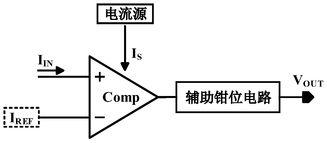
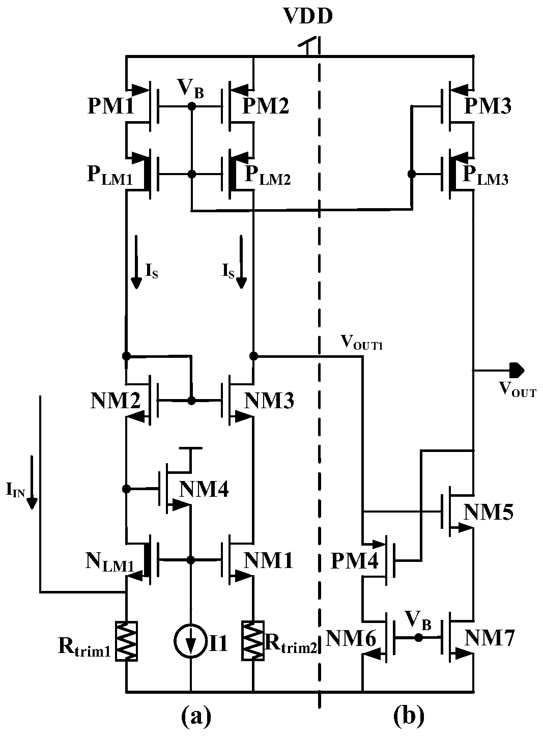
[0030] like figure 2 Shown is a schematic structural diagram of a low-power high-speed current comparator circuit proposed by the present invention, including a first NMOS transistor NM1, a second NMOS transistor NM2, a third NMOS transistor NM3, a fourth NMOS transistor NM4, a first low Threshold NMOS transistor N LM1 , the first PMOS transistor PM1, the second PMOS transistor PM2, the first low threshold PMOS transistor P LM1 , the second low threshold PMOS transistor P LM2 , the first current source I1, the first trimming resistor R trim1 and the second trimming resistor R trim2 , where the first low-threshold NMOS transistor N LM1 It is a depletion transistor; the first low-threshold NMOS transistor N LM1 The source of the current comparator circuit is used as the input terminal of the current comparator circuit and passed through t...


PUM


Abstract

The invention discloses a low-power-consumption high-speed current comparator circuit. Two NMOS (N-channel metal oxide semiconductor) tubes with different threshold voltages, namely a first low-threshold NMOS tube and a first NMOS tube, are used as input geminate transistors of a comparator; the input current flows into a source resistor of the first low-threshold NMOS; when the input current reaches a threshold value, the first NMOS tube NM1 is opened so as to pull down the drain electrode of the first NMOS tube NM1, a comparison signal VOUT1 generated by the comparator is turned over, and the threshold value of the input current is determined by the difference between the threshold voltages of the input geminate transistors and the trimming resistor. According to the invention, the voltage conversion of the input current, the generation of the reference level and the signal comparison are realized in one combined structure, so that the power consumption is saved, and the zero drift along with the temperature is realized. In addition, in order to further improve the speed, an auxiliary clamping module is further arranged, and the output voltage of the comparator is clamped at a voltage lower than that of the power supply by utilizing the clamping effect, so that the overturning speed of the comparator is increased.

Description

technical field [0001] The invention belongs to the technical field of analog circuit comparators, in particular to a source input current comparator circuit with low power consumption and high speed. Background technique [0002] In the field of analog power supply switching power supply, the current mode control circuit has the following advantages over the voltage mode control circuit: (1) high speed; (2) smaller chip area; (3) low power supply voltage and Power consumption; (4) Compatible with digital integrated circuit technology. As the basic unit of the current mode signal processing circuit, the current comparator plays an important role in the design of the integrated circuit. For the over-current protection design of the switching power supply, the over-current comparator is used as a part of the over-current protection circuit, and its performance directly affects the stability and reliability of the system. Since the rising slope and falling slope of the induct...

Claims


Application Information

Patent Timeline
IPC IPC(8): H03K5/24H03K3/012
CPCH03K3/012H03K5/2472
Inventor 周泽坤王佳文金正扬王韵坤张波
Owner UNIV OF ELECTRONIC SCI & TECH OF CHINA
Features
  • R&D
  • Intellectual Property
  • Life Sciences
  • Materials
  • Tech Scout
  • Unparalleled Data Quality
  • Higher Quality Content
  • 60% Fewer Hallucinations
Learn More