System and method for collaborative removal of mercury and sulfur dioxide from flue gas

A sulfur dioxide and flue gas technology, applied in chemical instruments and methods, separation methods, gas treatment, etc., to achieve the effects of pressure reduction, small space occupation, and convenient equipment installation

Pending Publication Date: 2019-10-18
BEIJING SPC ENVIRONMENT PROTECTION TECH
View PDF0 Cites 2 Cited by
  • Summary
  • Abstract
  • Description
  • Claims
  • Application Information

AI Technical Summary

Problems solved by technology

[0006] In order to solve the limitations of existing methods for synergistically removing multiple pollutants, the present invention provides a system and method for synergistically removing mercury and sulfur dioxide from flue gas

Method used


Image

  • System and method for collaborative removal of mercury and sulfur dioxide from flue gas
  • System and method for collaborative removal of mercury and sulfur dioxide from flue gas
  • System and method for collaborative removal of mercury and sulfur dioxide from flue gas

Examples


Embodiment 1

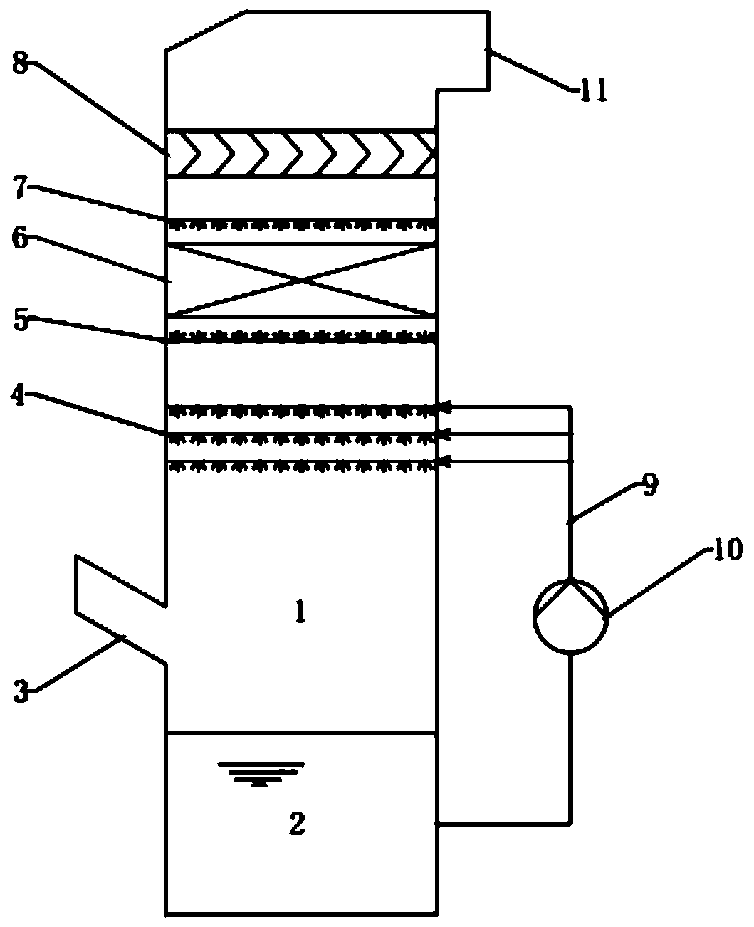
[0040] refer to figure 1 , the treatment flue gas volume is 3m 3 / h, SO before flue gas purification 2 The concentration is 2500~3000mg / m 3 , NOx concentration is 40~50mg / m 3 , the concentration of zero-valent mercury is 19.7μg / m 3 . Limestone slurry is used as the absorbing fluid.

[0041] First, the flue gas is treated without a composite adsorption catalyst, and the SO in the flue gas at the outlet of the system 2 The concentration is 20~30mg / m 3 , the desulfurization efficiency is about 99%, and the mercury emission concentration is consistent with the import and export mercury concentration.

[0042] When a composite adsorption catalyst is installed in the system, the SO in the flue gas at the outlet of the system 2 About 4mg / m 3 , to further remove about 84% of SO 2 , the installation of the composite adsorption catalyst layer increases the total desulfurization rate of the system from the original 99% to 99.8%; at the same time, the mercury concentration at th...

Embodiment 2

[0044] refer to figure 1 , extracting 9000Nm from the flue gas of a 600MW coal-fired unit 3 / h flue gas, its flue gas component is SO 2 The concentration is 4500~5200mg / m 3 , NOx concentration is 18~35mg / m 3 , the total mercury concentration is 10-20μg / m 3 , CO 2 The concentration is about 11.7%, and the oxygen concentration is about 5.6%.

[0045] Similar to Example 1, the raw flue gas is firstly treated without a composite adsorption catalyst, and the SO in the flue gas at the outlet of the system 2 The concentration is 20~30mg / m 3 , the desulfurization efficiency is about 99.4%, and the mercury emission concentration is about 7-14μg / m 3 , the mercury removal efficiency is about 30%

[0046] When a composite adsorption catalyst is installed in the system, the SO in the flue gas at the outlet of the system 2 About 6~10mg / m 3 , to further remove about 68% of SO 2 , the installation of the composite adsorption catalyst layer increases the total desulfurization rate o...


PUM


Abstract

The invention relates to a system and method for collaborative removal of mercury and sulfur dioxide from flue gas. The system can utilize the existing traditional flue gas desulfurization tower or washing tower, in which a slurry pool, an inlet flue, a slurry spray layer, a lower washing layer, a composite adsorption catalyst layer, an upper washing layer, a demister and an outlet flue are arranged from the bottom up in order. According to the invention, a composite adsorption catalyst layer and a washing layer are added above the slurry spray layer, while the composite adsorption catalyst adsorbs mercury in flue gas, sulfur dioxide in the flue gas is catalyzed for oxidization into sulfuric acid liquid drops, and then the generated sulfuric acid liquid drops are discharged from the composite adsorption catalyst layer by means of spray washing. Compared with other traditional flue gas mercury removal methods like adsorbent jet technology or activated coke / activated carbon dry process integration technology, the system has the advantages of simple structure, easy installation, small floor area and low operation cost, and also has the function of further improving the removal rate ofsulfur dioxide.

Description

technical field [0001] The invention relates to a system and method for synergistically removing mercury and sulfur dioxide in flue gas, which has a good synergistic removal function for mercury and sulfur dioxide in flue gas of thermal power plants. It belongs to the field of air pollution flue gas treatment and environmental protection. Background technique [0002] Coal-fired power generation, industrial boiler combustion, waste incineration, metal smelting, steel manufacturing and other industries will produce a large amount of industrial waste gas, which contains many air pollutants, such as sulfur oxides (SO 2 , SO 3 ), nitrogen oxides (NO x ), mercury (Hg) and particulate matter (PM). China has successively issued air pollutant emission standards for key industries, strictly restricting the emission of sulfur oxides, nitrogen oxides, mercury, dust and other pollutants. [0003] At present, the methods of synergistic removal of multi-component pollutants such as me...

Claims


Application Information

Patent Timeline
IPC IPC(8): B01D53/80B01D53/50B01D53/86B01D53/64
CPCB01D53/80B01D53/502B01D53/8665B01D53/8609B01D2257/602B01D2258/0283
Inventor 史丽羽许昌日郝向宇王玉山程俊峰刘英华
Owner BEIJING SPC ENVIRONMENT PROTECTION TECH
Why Eureka
Try Eureka