Tool damage online and in-situ detection system in clean cutting environment and method

A detection system and cleaning system technology, applied in manufacturing tools, measuring/indicating equipment, metal processing equipment, etc., can solve the problem of unfavorable flexible manufacturing system production and economic benefits improvement, unable to detect tool grinding/broken state changes process, the lack of visual system protection devices and tool cleaning devices, etc., to improve production efficiency and economic benefits, improve tool damage detection efficiency and reliability, and improve detection accuracy.

Pending Publication Date: 2019-10-18
NANJING UNIV OF SCI & TECH
View PDF3 Cites 19 Cited by
  • Summary
  • Abstract
  • Description
  • Claims
  • Application Information

AI Technical Summary

Problems solved by technology

[0003] Chinese Patent Publication No. CN102564314A discloses an orthogonal visual detection system for detecting the wear state of end mills. This detection system needs to stop the machine and disassemble the tool for detection in the laboratory, which occupies production man-hours and is not conducive to the production efficiency and economy of the flexible manufacturing system. The benefit is improved, and the state change process of tool grinding/damage in the processing process cannot be detected; Chinese Patent Publication No. CN106840028A discloses an in-situ measurement method and device for tool wear, and the visual inspection system is installed on the side of the machine tool tool to detect Inspection, the visual inspection system is fixed, it is impossible to realize multi-angle image acquisition of the tool, the detection of the tool

Method used


Image

  • Tool damage online and in-situ detection system in clean cutting environment and method
  • Tool damage online and in-situ detection system in clean cutting environment and method
  • Tool damage online and in-situ detection system in clean cutting environment and method

Examples


Embodiment Construction

[0022] The present invention will be further introduced below in conjunction with the accompanying drawings and specific embodiments.

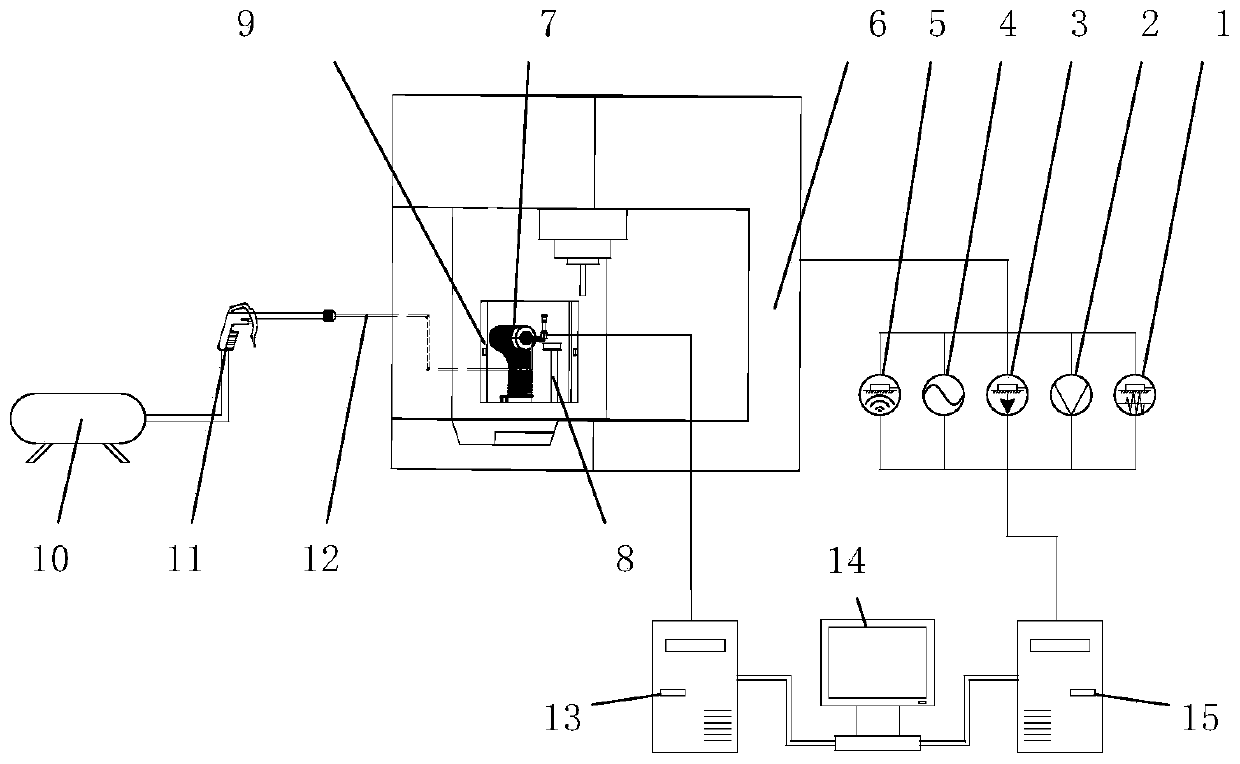
[0023] combine Figure 1-Figure 6 , an online and in-position detection system for tool damage in a clean cutting environment of the present invention, comprising an online prediction and identification system, an in-position detection system, a data acquisition card 15, an image acquisition card 13, a cleaning system, and a computer 14;

[0024] The online prediction and recognition system includes a vibration sensor 1, a voltage sensor 2, a force sensor 3, a current sensor 4, and an acoustic emission sensor 5; the vibration sensor 1 is installed near the cutting position of the machine tool machining center 6 or at the tool handle, Used for real-time measurement of vibration near the cutting position during machine tool processing; the voltage sensor 2 and current sensor 4 are installed at the control cabinet of the machine tool machining ce...


PUM


Abstract

The invention discloses a tool damage online and in-situ detection system in a clean cutting environment and a method. The system comprises an on-line pre-judgment and recognition system, an in-situ detection system, a cleaning system for cleaning a tool, and a computer, wherein the on-line pre-judgment and recognition system is used for measuring the vibration amount of a cutting position in realtime, the change value of a main shaft voltage and the current, the change value of the cutting force and a sound signal, the in-site detection system is used for acquiring a side edge image and a bottom edge image of the tool in-site, and the computer is used for carrying out time domain feature and frequency domain feature extraction and data fusion on signals collected by the on-line pre-judgment and recognition system; whether the data are abnormal or not is judged primarily; and the image is further processed to judge the damage type and damage degree of the tool. According to the method, the tool damage is preliminarily judged through the on-line pre-judgment and recognition system, then the damage type and damage degree of the tool are judged, so that accurate detection of tool abrasion is realized.

Description

technical field [0001] The invention belongs to the technical field of tool detection, in particular to a system and method for on-line and in-position detection of tool damage in a clean cutting environment. Background technique [0002] In the process of automated mechanical processing, monitoring tool wear status is one of the important means to reduce manufacturing costs, reduce manufacturing environmental hazards, and ensure the normal and efficient operation of the manufacturing system and product quality. Tool wear has a significant impact on the processing accuracy, processing quality and processing efficiency of the product. If the tool wear is not discovered in time, it will lead to scrapped parts, machine downtime, machine damage, and even workpiece breakage, which directly affects processing and economic benefits. . Industrial statistics show that tool wear is the primary factor causing machine tool failures, and the resulting downtime accounts for 1 / 5 to 1 / 3 of...

Claims


Application Information

Patent Timeline
IPC IPC(8): B23Q17/09B23Q17/24B23Q11/00
CPCB23Q17/0957B23Q17/249B23Q11/0042
Inventor 王禹林叶祖坤濮潇楠查文彬陈超宇
Owner NANJING UNIV OF SCI & TECH
Why Eureka
Try Eureka