Method for improving bonding strength of anti-oxidation coating on surface of carbon-based or ceramic-based composite material

A technology of anti-oxidation coating and composite materials, which is applied in the field of improving the bonding strength of anti-oxidation coatings on the surface of carbon-based or ceramic-based composite materials, which can solve the problems of easy peeling, rapid consumption, and low bonding strength of coatings, and achieve small damage , Improve the effect of bonding strength

Active Publication Date: 2019-10-22
INST OF METAL RESEARCH - CHINESE ACAD OF SCI
View PDF6 Cites 9 Cited by
  • Summary
  • Abstract
  • Description
  • Claims
  • Application Information

AI Technical Summary

Problems solved by technology

The coating has low bonding strength, and it is easy to peel off under high and low tempera

Method used


Image

  • Method for improving bonding strength of anti-oxidation coating on surface of carbon-based or ceramic-based composite material
  • Method for improving bonding strength of anti-oxidation coating on surface of carbon-based or ceramic-based composite material
  • Method for improving bonding strength of anti-oxidation coating on surface of carbon-based or ceramic-based composite material

Examples


Embodiment 1

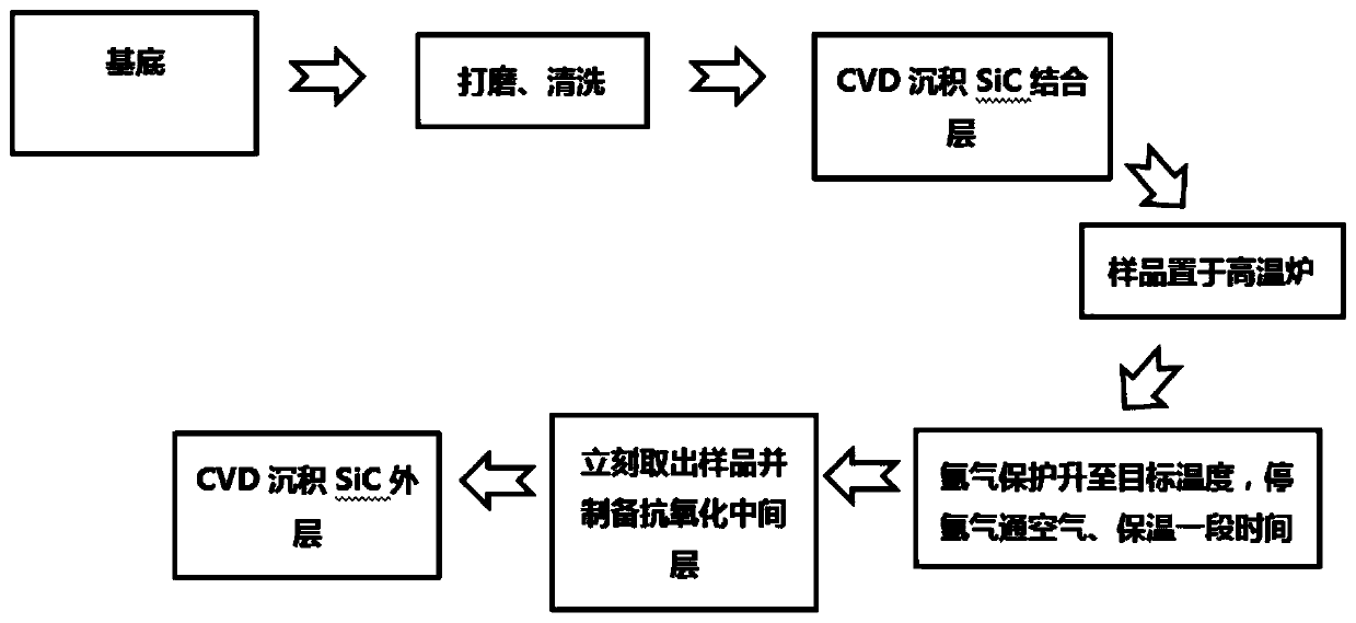
[0031] The process flow chart for improving the bonding strength of the anti-oxidation coating on the surface of the ceramic matrix composite material in this embodiment is as follows figure 1 As shown, the specific process is as follows:

[0032] First to C f / SiC samples were pretreated. Choose a density of 2.0g / cm 3 C f / SiC, polished with 400# diamond sandpaper, ultrasonically oscillated in distilled water for 80 minutes, and then rinsed repeatedly with distilled water; the cleaned C f / SiC was dried at 150°C for 24 hours for later use.

[0033] The preprocessed C f / SiC samples are placed in a graphite crucible and placed in a chemical vapor deposition furnace to deposit the SiC bonding layer. A small hole is drilled at the bottom of the graphite crucible to ensure gas circulation. The deposition temperature is 1100°C, the deposition pressure is 5mmHg, the flow rate of trichloromethylsilane (MTS) is 60g / h, and the flow rate of hydrogen gas is 0.03m 3 / h, argon flow r...

Embodiment 2

[0041] First to C f / C samples were pretreated. Choose a density of 1.9g / cm 3 C f / C, after polishing with 600# silicon carbide sandpaper, ultrasonically vibrate in distilled water for 70min, and then rinse repeatedly with distilled water; the cleaned C f / C at 150°C, dry for 24 hours for later use.

[0042] The preprocessed C f The / C sample is placed in a graphite crucible and placed in a chemical vapor deposition furnace for SiC bonding layer deposition. A small hole is drilled at the bottom of the graphite crucible to ensure gas circulation. The deposition temperature is 1000°C, the deposition pressure is 6mmHg, the flow rate of trichloromethylsilane (MTS) is 70g / h, and the flow rate of hydrogen gas is 0.04m 3 / h, argon flow rate 0.05m 3 / h. Take it out after 15 hours of deposition, turn it over and deposit it for another 15 hours. Increase the deposition temperature to 1100°C, and the hydrogen flow rate to 0.08m 3 / h, argon flow rate 0.1m 3 / h, after 20h of depo...


PUM


Abstract

The invention discloses a method for improving the bonding strength of an anti-oxidation coating on the surface of a carbon-based or ceramic-based composite material, and belongs to the technical field of anti-oxidation of carbon-based and ceramic-based composite materials. The method comprises: preparing a SiC bottom layer on the surface of a substrate material by using a CVD process; carrying out pre-oxidation treatment on the substrate material deposited with SiC to form silicon oxide on the surface; preparing a super-high temperature ceramic anti-oxidation middle layer on the surface of the pre-oxidized sample by using a slurry brushing-sintering process; and depositing a SiC outer layer on the surface of the sample. According to the present invention, with the pre-oxidation process, the bonding strength between the brushing middle layer and the SiC bottom layer can be effectively improved so as to obtain the high-bonding strength SiC/ZrB2-SiC/SiC three-layer composite anti-oxidation coating.

Description

technical field [0001] The invention relates to the technical field of oxidation resistance of carbon-based and ceramic-based composite materials, in particular to a method for improving the bonding strength of an anti-oxidation coating on the surface of carbon-based or ceramic-based composite materials. Background technique [0002] With high specific strength, high thermal conductivity, low thermal expansion coefficient, excellent high temperature mechanics and thermal shock resistance, carbon fiber reinforced carbon matrix composites and carbon fiber reinforced ceramic matrix composites have been widely used in aerospace, nuclear energy industry and civil fields. application. However, when carbon fiber-reinforced carbon-based or carbon-fiber-reinforced ceramic matrix composites are used in an aerobic environment above 450 °C, the carbon fibers inside the composite will be oxidized, resulting in a decrease in material performance. Oxidation coating technology can improve ...

Claims


Application Information

Patent Timeline
IPC IPC(8): C04B35/565C04B35/58C04B35/622C04B41/89
CPCC04B35/565C04B35/58078C04B35/62222C04B41/009C04B41/507C04B41/89C04B41/5059C04B35/80C04B35/83
Inventor 汤素芳胡成龙庞生洋唐鹏举李建
Owner INST OF METAL RESEARCH - CHINESE ACAD OF SCI
Why Eureka
Try Eureka