
A compound forming system and method for additive manufacturing and surface coating

A composite forming and surface coating technology, applied in the direction of processing and manufacturing, manufacturing tools, additive manufacturing, etc., can solve the problems of complex structure of parts, poor coating effect, difficult coating of parts, etc. Bottlenecks, the effect of avoiding blowholes

Active Publication Date: 2020-11-17
HUAZHONG UNIV OF SCI & TECH
View PDF9 Cites 0 Cited by
  • Summary
  • Abstract
  • Description
  • Claims
  • Application Information

AI Technical Summary

Problems solved by technology

[0013] The above four surface strengthening processes solve the problem of surface performance enhancement of parts and molds from different angles, but they also have difficulties in obtaining large thickness and high density coatings, and coating materials are prone to oxidation and phase transformation. Disadvantages, it is difficult to meet the needs of short-process manufacturing and high-temperature corrosion-resistant surfaces for high-end aerospace parts at the same time
[0014] In addition, parts in industries such as aerospace, energy and power have complex structures and have high requirements on their microstructure and surface properties. Cracking and porosity in the forming process of the material are unavoidable, and the surface coating process is carried out after the additive manufacturing of the part is completed. For complex parts, there will be problems such as difficult coating and poor coating effect. Features do not meet requirements

Method used


Image

  • A compound forming system and method for additive manufacturing and surface coating
  • A compound forming system and method for additive manufacturing and surface coating
  • A compound forming system and method for additive manufacturing and surface coating

Examples


Embodiment Construction

[0035] In order to make the object, technical solution and advantages of the present invention clearer, the present invention will be further described in detail below in conjunction with the accompanying drawings and embodiments. It should be understood that the specific embodiments described here are only used to explain the present invention, not to limit the present invention. In addition, the technical features involved in the various embodiments of the present invention described below can be combined with each other as long as they do not constitute a conflict with each other.

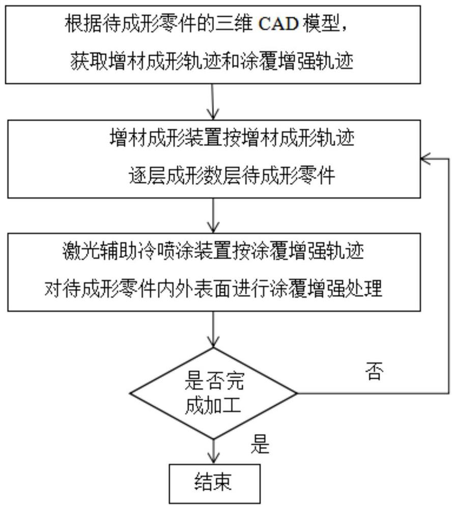
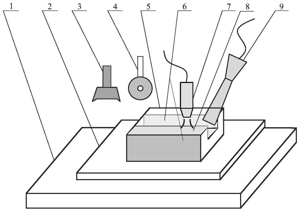
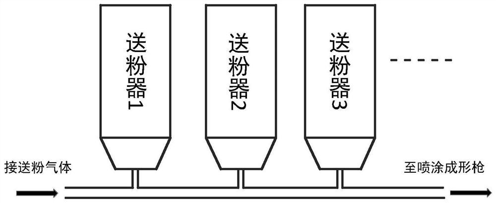
[0036] An embodiment of the present invention provides an additive manufacturing and surface coating composite forming system, such as figure 2 As shown, it includes an additive forming device 7, a laser-assisted cold spraying device 9 and a workbench 1, wherein the additive forming device 7 and the laser-assisted cold spraying device 9 are located above the workbench 1, and a substrate 2 is pl...


PUM


Abstract

The invention belongs to the field of multi-material composite additive manufacturing, and specifically discloses a composite forming system and method for additive manufacturing and surface coating, which includes an additive forming device, a laser-assisted cold spraying device and a workbench, and an additive forming device And the laser-assisted cold spraying device is located above the workbench. During processing, the additive forming device forms the parts to be formed layer by layer on the workbench. The laser-assisted cold spraying device performs coating enhancement on the inner and outer surfaces of the parts to be formed during the forming process. Thereby, the composite processing and manufacturing of the parts to be formed are jointly completed; on the basis of making full use of the advantages of the short-process additive manufacturing rapid prototyping parts, the present invention integrates the surface coating enhancement process into this system, which improves the composite additive manufacturing and surface quality of the parts. The efficiency of strengthening can overcome the technical bottleneck of direct additive manufacturing and surface coating compound forming for components with complex structures and high surface strengthening requirements.

Description

technical field [0001] The invention belongs to the field of multi-material composite additive manufacturing, and more specifically relates to a composite forming system and method for additive manufacturing and surface coating. Background technique [0002] Additive manufacturing methods for complex structural parts mainly include high-power laser deposition forming, electron beam free forming, plasma arc deposition and other forming methods. [0003] Among them, the high-power laser deposition forming uses a high-power laser to melt the metal powder sent to the substrate layer by layer, and rapidly solidifies and deposits it into shape, and finally obtains a near-final shape; Higher than selective laser sintered parts, but the forming efficiency, energy and material utilization are not high, it is difficult to achieve full density, equipment investment and operating costs are high (see literature A.J.Pinkkerton, L.Li, Effects of Geometry and Composition in Coaxial Laser De...

Claims


Application Information

Patent Timeline
IPC IPC(8): B22F3/105B22F3/24B33Y10/00B33Y30/00C23C24/04
CPCB22F3/24B33Y10/00B33Y30/00C23C24/04B22F2003/242B22F2003/247B22F10/00B22F12/55B22F10/28B22F10/362B22F12/52B22F10/66B22F10/25B22F2998/10B22F10/50C23C24/00Y02P10/25B22F3/115B23K26/342B23K15/0086B23K10/027C23C24/082C23C24/087B23K26/144B29C64/314B29C64/153B29C64/188B29C64/245B29C64/255B33Y40/10
Inventor 张海鸥胡晓圻戴福生王桂兰
Owner HUAZHONG UNIV OF SCI & TECH
Learn More