Constant Temperature Crystal Oscillator Aging Automatic Test System

A constant temperature crystal oscillation and automatic test system technology, applied in the direction of instruments, measuring electronics, measuring devices, etc., can solve the problems of difficult test system transformation, increased test cost, and high temperature in the test room, so as to improve test ability and work efficiency, reduce The effect of test cost and high integration

Active Publication Date: 2021-04-30
HEBEI FAREAST COMM SYST ENG
View PDF12 Cites 0 Cited by
  • Summary
  • Abstract
  • Description
  • Claims
  • Application Information

AI Technical Summary

Problems solved by technology

The entire test system uses a large number of coaxial cables, radio frequency program-controlled switches, bloated structure and low space utilization
At the beginning of the design of the test system, the problem of system compatibility was not considered. When the production capacity of the constant temperature crystal oscillator changes, it is necessary to change the test board with different packages and voltages. It is very difficult to modify the test system.
At present, the test system is an open structure. After a large number of constant temperature crystal oscillators are powered on, their own current consumption is high, the test power consumption is large, the cost is high, and the temperature of the entire test room will be very high. All test equipment includes Radio frequency program-controlled switches, frequency counters, switching power supplies, rubidium atomic clocks, and control computers all work at a very high temperature, which greatly reduces the service life of the equipment and indirectly increases the cost of testing
The entire test system uses a large number of interfaces, including frequency signal transmission interfaces and control signal transmission interfaces. When used in a high-temperature environment for a long time, the reliability of these interfaces becomes low, and poor contact often occurs. Testers need a lot of energy to solve These test problems reduce productivity

Method used


Image

  • Constant Temperature Crystal Oscillator Aging Automatic Test System
  • Constant Temperature Crystal Oscillator Aging Automatic Test System
  • Constant Temperature Crystal Oscillator Aging Automatic Test System

Examples


Embodiment Construction

[0037]The present invention is further explained below in connection with the embodiments, and the object is merely understood, and therefore, the specific embodiments are not limited to the scope of the invention.

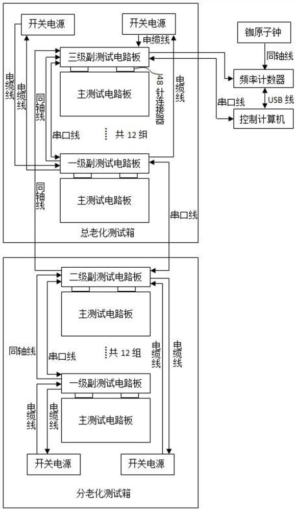
[0038]Seefigure 1 The constant temperature crystal oscillator aging test system of the present invention includes: a total aging test box, multiple division of aging test box, control computer, switching power supply, frequency counter, and 铷 atom clock, the total aging test box includes 12 main test circuit boards, 1 three-level sub-test circuit board, 11 piece secondary sub-circuit test board, the interior of the split aging test box included 12 primary test circuit boards, 1 second secondary subtraction circuit board, 11 sets of secondary circuit test boards.铷 The atomic clock output signal is connected to the frequency counter external frequency standard input interface via the coaxial line, providing an external frequency standard for the counter, allowing the counter...


PUM


Abstract

The invention discloses an aging automatic test system for a constant temperature crystal oscillator, which comprises an aging test box, a control computer, a frequency counter and a rubidium atomic clock. The aging test box contains an insulating layer, which can reduce the working environment temperature of the test equipment and prolong its service life. It can also increase the working environment temperature of the constant temperature crystal oscillator, reduce the working current and save the test cost. The aging test box is equipped with several main Test circuit board and several sub-test circuit boards. The main test circuit board includes an oven-controlled crystal oscillator and a frequency transmission circuit. The secondary test circuit board includes a frequency transmission circuit, a voltage protection circuit, a switching power supply voltage adjustment circuit, a voltage control voltage circuit, and a communication level conversion circuit. The testing device of the present invention can complete functions such as automatic collection of frequency data of large-scale constant temperature crystal oscillators, automatic adjustment of power supply voltage, automatic test of power supply voltage, overvoltage protection of power supply voltage, automatic adjustment of voltage control voltage and automatic timing on and off of constant temperature crystal oscillators.

Description

Technical field[0001]The present invention relates to the frequency testing of crystal oscillators, and more particularly to a large-scale thermostatic crystal oscillator aging automatic test system.Background technique[0002]At present, the constant temperature crystal oscillator aging automatic test system is a test frame structure, mainly using a radio frequency program to turn the frequency signal, and the fixed voltage switching power supply is a constant temperature crystal oscillator power supply. The constant temperature crystal oscillator is inserted on the power-on plate, and the output signal is connected to the radio frequency program control switch by the coaxial line, and the radio frequency program is to switch to the program-controlled device that switchable-to-one pathway through the physical relay. The radio frequency program control switch is finally final Connect to the frequency counter. The entire test system uses a large number of coaxial lines, radio frequency...

Claims


Application Information

Patent Timeline
Patent Type & Authority Patents(China)
IPC IPC(8): G01R23/02G01R31/00
CPCG01R23/02G01R31/00
Inventor 韩文博任勇森贾伟琦白毅赵斌刘文雅刘搏
Owner HEBEI FAREAST COMM SYST ENG
Why Eureka
Try Eureka