Method for nano vacuum coating of reflective cup

A technology of vacuum coating and reflector, which is applied in vacuum evaporation coating, sputtering coating, ion implantation coating and other directions, can solve the problem that the requirements of reflector cups of lamps cannot be well met, the stability of artificial spraying process is poor, and the reflection is reduced. Cup reflectivity and other issues, to achieve the effect of good industrial development prospects, good market competitiveness, and good quality

Inactive Publication Date: 2019-12-13
韦立
View PDF2 Cites 1 Cited by
  • Summary
  • Abstract
  • Description
  • Claims
  • Application Information

AI Technical Summary

Problems solved by technology

[0003] At present, the preparation of the protective film of lamps and lanterns mostly adopts the artificial surface spraying organic layer as the protective film, because the process is not completed under vacuum conditions, so the surface of the aluminum film will be corroded, and the coating will also be polluted to varying degrees, reducing the overall The performance of the car lamp; more importantly, the sprayed organic coating has poor chemical stability. Under the environment of high temperature and ultraviolet light, its transmittance will be greatly reduced, thereby reducing the reflectivity of the reflector cup
In addition to the poor stability of the artificial spraying process, the reflectivity of the reflective cup prepared by this process is about 75%, which can no longer meet the requirements of the lamp for the reflective cup.

Method used


Image

  • Method for nano vacuum coating of reflective cup

Examples


Embodiment Construction

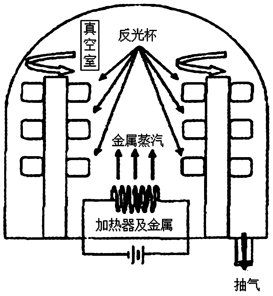
[0024] The present invention will be further described below in conjunction with the accompanying drawings.

[0025] A method for nanometer vacuum coating of reflective cups, comprising the following steps:

[0026] (1) Pre-treatment: Clean the oil and release agent on the surface of the reflector, and activate the surface of the reflector;

[0027] (2) Drying and electrostatic dust removal: After drying the pre-treated reflective cup, the electrostatic field is used to ionize the gas so that the dust particles are charged and adsorbed to the electrode;

[0028] (3) Silicone oil evaporation for the first time: Fix the reflective cup processed in step (2) on the fixture and install it in the vacuum chamber of the evaporation coating machine to coat a layer of silicone oil. The thickness of the silicone oil is 2.5-3.0μm;

[0029] (4) Evaporation: Coating the reflective cup coated with silicone oil, the thickness of the coating is 50-60 μm;

[0030] (5) Silicone oil evaporation...


PUM

PropertyMeasurementUnit
thicknessaaaaaaaaaa
thicknessaaaaaaaaaa
reflectanceaaaaaaaaaa

Abstract

The invention discloses a method for nano vacuum coating of a reflective cup. The method comprises the following steps: (1) pre-treatment: cleaning oil stains and a release agent on the surface of thereflective cup and activating the surface of the reflective cup; (2) drying and electrostatic dust collection: after drying the pre-treated reflective cup, ionizing gas by means of an static electricfield to absorb dust particles to an electrode in an electrified manner; (3) first time evaporation of silicone oil: fixing the reflective cup treated in the step (2) to a clamp and mounting the reflective cup in a vacuum chamber of an evaporative coating machine for plating silicone oil, wherein the thickness of the silicone oil is 2.5-3.0 [mu]m; (4) evaporation: coating the reflective cup plated with the silicone oil, wherein the thickness of the coating is 50-60 [mu]m; (5) second time evaporation of silicone oil: plating silicone oil to the evaporated reflective cup, wherein the thicknessof the silicone oil is 2.5-3.0 [mu]m; and (6) inspection and packaging: inspecting the reflective cup treated in the step (5) and packaging and putting qualified products in storage.

Description

technical field [0001] The invention relates to the technical field of vacuum coating, in particular to a method for nanometer vacuum coating of reflective cups. Background technique [0002] The optical surface of some optical parts needs to be plated with one or more layers of thin film by physical or chemical methods, so that the characteristics of reflected light or transmitted light of the light passing through the surface will change, and the surface of the tool used in many mechanical processing also needs to deposit 1 Layer dense, combined with a firm superhard coating to harden it, prolong its service life, improve cutting efficiency, thereby improving the precision and smoothness of the processed parts. At present, vacuum coating as a physical coating method, especially the nanoscale ultra-thin film production technology, has been widely used in high-tech fields such as electric vacuum, radio, optics, atomic energy, space technology, and information technology and ...

Claims


Application Information

Patent Timeline
Patent Type & Authority Applications(China)
IPC IPC(8): C23C14/26C23C14/12C23C14/20
CPCC23C14/12C23C14/20C23C14/26
Inventor 韦立
Owner 韦立
Why Eureka
Try Eureka