Microporous ceramic heating device for atomizer and preparation process thereof

A technology of microporous ceramics and heating devices, which is applied in the direction of electric heating devices, ohmic resistance heating, tobacco, etc., can solve the problems of overheating and fusing, poor and uneven edge flatness, and affecting the atomization effect, etc., to meet the requirements of heating and heating Demand, reduce temperature gradient effect, good effect of consistent temperature rise performance

Active Publication Date: 2022-07-19
INNOKIN TECH
View PDF9 Cites 0 Cited by
  • Summary
  • Abstract
  • Description
  • Claims
  • Application Information

AI Technical Summary

Problems solved by technology

Generally, one or two heating wires are laid on the heating surface 4. Although some are bent, they still cannot achieve a good uniform atomization effect when placed on the ceramic heating surface 4, so the temperature gradient problem is not very good. the solution
like figure 1 The length and width of the ceramic surface are 5 and 4 mm, and when the width of the heating wire is 0.6 mm, except for two parallel heating wires of 0.6 mm, the rest is used as a heating area, and some points are close to 1 mm from the heating wire, so Will affect the atomization effect
[0009] Secondly, since the thick film resistance wire is formed by sintering the metal paste screen, the uniformity of the resistance wire is not perfect due to the problems of printing technology and sintering deformation, and it is not as uniform as the alloy wire resistance.
formed as image 3 In the state shown, the edge of the printed heating wire 3 is in an alternating state of flange and concave edge 5, that is, the edge is relatively poor and uneven, and there will always be some places that are narrow or uneven in thickness. These unevenness lead to electrification When the current density is uneven, the heating temperature is inconsistent, and the temperature difference will cause the deformation of the resistance wire itself, resulting in warping, bursting and other phenomena, and finally lead to fusing
The local damage of the thick film heating resistor is basically caused by the local concentrated overheating caused by the uneven width
Therefore, although the current thick film resistor technology can print wires to a relatively thin level, such as 0.1 mm, the 0.1 mm wires can be used as ordinary wires and resistors for resistance heating due to high heating temperature. , a thick film resistance wire of such a size is easy to be partially overheated and fused due to heating. In fact, it has been found through experiments that when the width of the thick film printed resistance used for heating is less than 0.5 mm, it is basically the result of a second-off power.
[0010] Thirdly, since the thick-film printed heating wire is printed on the heating surface of the ceramic substrate through the screen, the surface of the wire protrudes from the heating surface, and the protruding wire part is difficult to contact with the e-liquid, which leads to dry burning phenomenon, and the heating wire The thickness will also affect the heating effect
The screen printing directly forms the heating wire pattern, so this printing method cannot be printed after setting grooves on the ceramic surface, otherwise it is difficult to directly correspond the screen pattern to the groove during printing

Method used


Image

  • Microporous ceramic heating device for atomizer and preparation process thereof
  • Microporous ceramic heating device for atomizer and preparation process thereof
  • Microporous ceramic heating device for atomizer and preparation process thereof

Examples


Embodiment 1

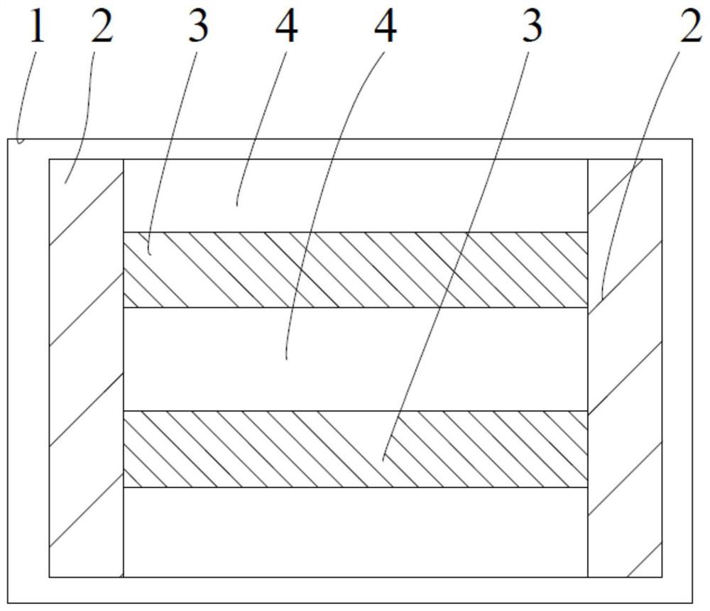
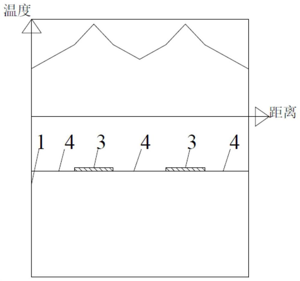
[0037] Example 1: as Figure 4 As shown, this embodiment is a microporous ceramic substrate thick-film printing heating device, and a resistance heating wire 3 is formed on the heating surface 1 of the microporous ceramic substrate by thick-film printing. The resistance heating wires 3 are arranged in parallel with a plurality of resistance wires, and are evenly distributed on the heating surface 1 of the ceramic substrate in parallel. The resistance wire 3 is a thin strip-shaped structure with a width of 0.1 mm and a thickness of 0.03 mm. The resistance wires 3 are evenly arranged on the heating surface 1, and the number of the heating wires 3 is 12. Both ends of the resistance wire 3 are connected to the heating electrode 2 in parallel, and the heating wires 3 are arranged in parallel. At this time, an atomized heating area 4 is formed in the area of ​​the parallel heating wires 3 and the edge area. In the heating area 4, the width between the two adjacent heating wires 3 ...

Embodiment 2

[0050] Example 2: as Image 6 As shown in the figure, this example is made with the same ceramic matrix, the same slurry, and the same process as in Example 1. The width of the heating wire is controlled at 0.2 mm, the line spacing is 0.4 mm, and any point in the heating area is to the heating guide edge. The distance is not more than 0.2 mm. The resistance wire thickness is still 0.03mm. However, due to the increase in line width, the number of resistor lines needs to be reduced accordingly. for example Figure 4 12 of them, here reduced to 6, have the same resistance value as Example 1. Each resistance is 10.67 ohms, and the overall heating resistance is 1.78 ohms.

Embodiment 3

[0051] Example 3: This example is prepared by using the same ceramic substrate, the same slurry, and the same process as in Example 1. The width of the resistance line is controlled at 0.15 mm, the line spacing is still 0.3 mm, and the thickness of the resistance line is still 0.03 mm . However, due to the increase in line width, the number of resistor lines needs to be reduced accordingly. for example Figure 4 Of the 12, this is reduced to 8. have the same resistance value. Each resistance is 14.22 ohms, and the overall heating resistance is 1.78 ohms.


PUM

PropertyMeasurementUnit
widthaaaaaaaaaa
thicknessaaaaaaaaaa
thicknessaaaaaaaaaa

Abstract

The invention discloses a microporous ceramic heating device for an atomizer, which comprises a microporous ceramic substrate and a heating wire arranged on the microporous ceramic substrate. Wherein, the heating wire is a thin strip-shaped heating wire formed after thick film printing, sintering and molding, and then processing by mechanical cutting, chemical etching or laser lithography. The heating wires are evenly distributed on the heating surface of the ceramic substrate. The preparation process of the microporous ceramic heating device for the atomizer of the present invention includes the following steps: setting a microporous ceramic substrate, the microporous ceramic substrate having a heating surface, and performing thick film printing on the heating surface of the microporous ceramic substrate , drying, sintering treatment. Then, the sintered thick film printing part is processed by mechanical cutting, chemical etching or laser lithography to form thin strip heating wires with a predetermined shape.

Description

technical field [0001] The invention relates to a microporous ceramic heating device for an atomizer, in particular to a microporous ceramic substrate heating device using a thick-film printed resistor as a heating material. [0002] The present invention also relates to a preparation process of the above-mentioned microporous ceramic heating device. Background technique [0003] In the field of electronic cigarette technology, the use of microporous ceramics as the oil-conducting medium has become the mainstream configuration. In the electronic cigarette atomizer that uses microporous ceramics as the oil-conducting medium, it is necessary to make the resistance wire as close as possible to the electronic cigarette liquid in the microporous ceramics. Although the resistance wire away from the e-liquid will also generate heat, when the microporous ceramic is used as the oil-conducting component, the precipitated e-liquid cannot be separated from the surface of the micro-poro...

Claims


Application Information

Patent Timeline
Patent Type & Authority Patents(China)
IPC IPC(8): A24F40/46A24F40/70A24F40/40H05B3/28
CPCH05B3/283
Inventor 方勇谭会民胡廷东
Owner INNOKIN TECH
Why Eureka
Try Eureka