Fretting wear test device based on ultrasonic technology

A technology of fretting wear and testing equipment, which is applied in measuring equipment, vibration testing, testing wear resistance, etc., can solve problems such as poor anti-interference ability, low precision, low reliability, and large driving force, and achieve reliability and The effect of high precision, shortened test time, and reduced time cost

Inactive Publication Date: 2020-01-17
NORTHWESTERN POLYTECHNICAL UNIV
View PDF12 Cites 3 Cited by
  • Summary
  • Abstract
  • Description
  • Claims
  • Application Information

AI Technical Summary

Problems solved by technology

[0005] Chinese Patent CN 101017129A "Multifunctional Micro Friction and Wear Testing Machine", this testing machine uses a cantilever elastic plate and a connecting rod to articulate the driving device and movement device, and uses a motor to directly drive the connecting rod to push the sliding table or rotating table to make a reciprocating straight line with a small amplitude Movement or twisting, large driving force, large amplitude, and good stability can realize different forms of fretting wear tests, but the frequency is not high, and the structure is complex and there are many moving parts, resulting in low accuracy and reliability
[0006] Chinese patent CN 103308407B "High-frequency reciprocating fretting friction and wear testing machine", according to the small load loading requirements, the test force is loaded on the test piece by means of magnetic loading, and the principle of electromagnetic induction is used to construct a magnetic drive mechanism to achieve displacement. Reciprocating movement, the vibration amplitude can be adjusted by adjusting the current, it has the characteristics of high degree of automation, low power consumption, and good adaptability to small loads, but its structure is relatively complex, the anti-interference ability is poor, and it is not suitable for large load loading requirements

Method used


Image

  • Fretting wear test device based on ultrasonic technology
  • Fretting wear test device based on ultrasonic technology
  • Fretting wear test device based on ultrasonic technology

Examples


Embodiment Construction

[0024] This embodiment is a fretting wear test device based on ultrasonic technology.

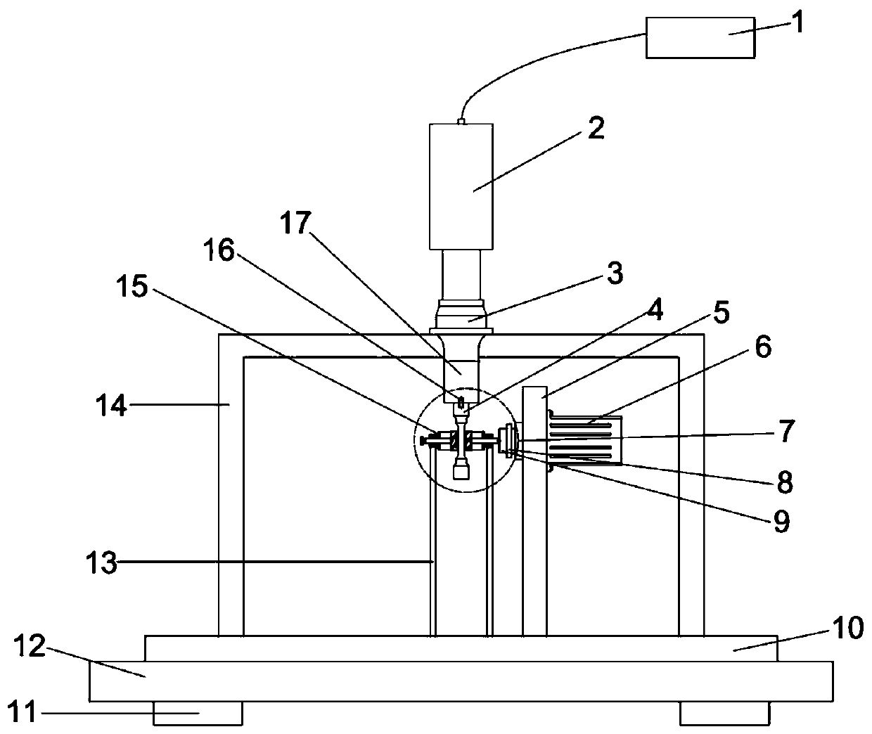
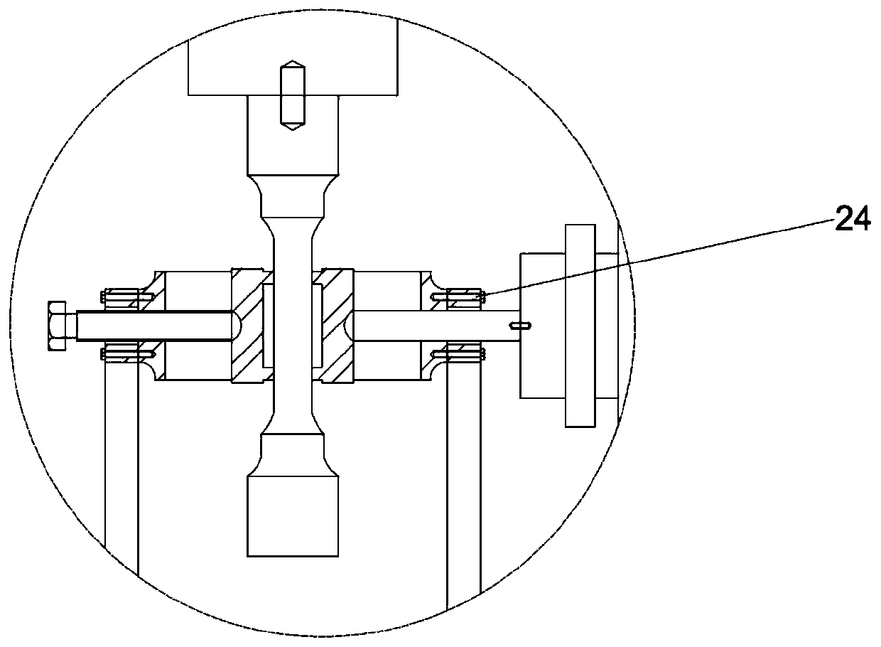
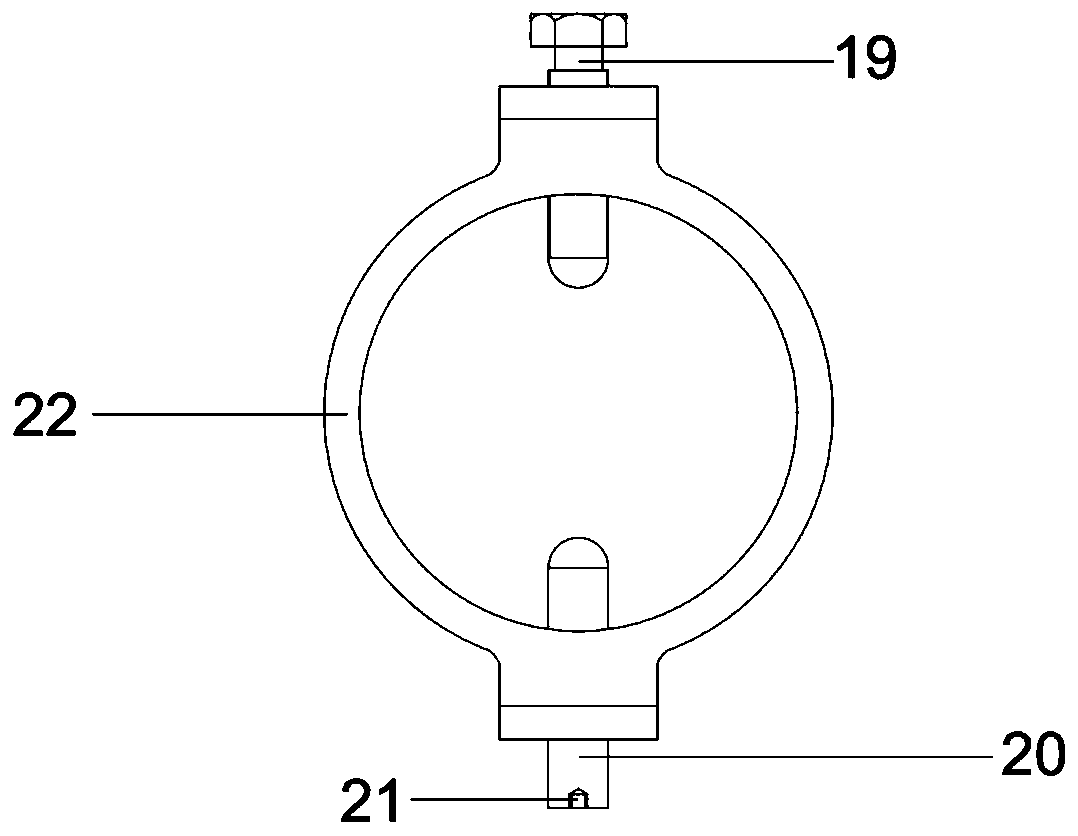
[0025] refer to Figure 1 to Figure 5 , this embodiment is based on the ultrasonic technology fretting wear test device, which consists of an ultrasonic generator 1, an electric cylinder bracket 5, a servo electric cylinder 6, an electric cylinder joint 7, a force sensor 8, a pad 9, a fixed platform 10, a support pad 11, The bottom plate 12, the loading device bracket 13, the amplifier bracket 14, the loading device 15, the driving device and the data acquisition device are composed; wherein, the bottom plate 12 is made of high-strength steel, and the bottom plate 12 provides support for each component; the bottom of the bottom plate 12 is equipped with a support Pad 11, the supporting pad 11 is used for height adjustment, by adjusting the height of the supporting pad 11, the bottom plate is always in a horizontal state. The fixed platform 10 is located at the top of the base plate, and th...


PUM


Abstract

The invention discloses a fretting wear test device based on an ultrasonic technology. The fretting wear test device is composed of an ultrasonic generator, a servo electric cylinder, a force sensor,a loading device, a driving device and a data acquisition device; a loading head is pushed by the servo electric cylinder to make contact with fretting pads to apply positive pressure to a test part;and the force sensor acquires a positive signal, sets a computer data processing device to form closed loop feedback control with the acquired positive pressure signal to keep a load applied by the loading device constant. The fretting wear test device is simple in structure and convenient to operate, the various parts are fixed and supported by a bottom plate and a fixing platform, the stabilityis good, and the advantages of being high in reliability and precision are achieved; and a transducer is adopted to convert ultrasonic signals into reciprocating linear mechanical motion of a vibrating head, vibration displacement is amplified by an amplifier to serve as an excitation source for forming fretting wear between a friction pair, the vibration frequency is high, the amplitude is adjustable, the test time can be shortened, and the test cost can be reduced.

Description

technical field [0001] The invention relates to a wear test device, in particular to a fretting wear test device based on ultrasonic technology, and belongs to the technical field of fretting friction and wear testing of materials. Background technique [0002] Fretting refers to the relative motion of two contact surfaces with extremely small amplitude on the order of microns, which usually exists in a nearly fastened mechanical fitting under a vibration condition. Fretting can lead to wear of the contact surface, component occlusion, loosening, power loss, noise increase or pollution source formation; fretting can also accelerate the initiation and expansion of local fatigue cracks, greatly reducing the fatigue life of the overall component. [0003] Fretting wear is the wear that occurs on the surface of two contact bodies with a very small displacement amplitude. Generally, the relative displacement amplitude of the two contact bodies is less than 300 μm. Fretting damag...

Claims


Application Information

Patent Timeline
Patent Type & Authority Applications(China)
IPC IPC(8): G01N3/56G01M7/02
CPCG01M7/00G01N3/56
Inventor 秦志薛红前李斌靳泓睿
Owner NORTHWESTERN POLYTECHNICAL UNIV
Why Eureka
Try Eureka