Multi-robot precision machining system and method for large-aperture integral optical element

An optical element and precision machining technology, applied in the field of large-diameter integral optical element multi-robot precision machining system, which can solve the problems of high cost and long production cycle.

Active Publication Date: 2020-01-31
INST OF OPTICS & ELECTRONICS - CHINESE ACAD OF SCI
View PDF15 Cites 15 Cited by
  • Summary
  • Abstract
  • Description
  • Claims
  • Application Information

AI Technical Summary

Problems solved by technology

[0004] The purpose of the present invention is to solve the problem of long production cycle and high cost of large-diameter integral optical element processing equipment, and to effectively improve the production efficiency of large-diameter integral optical element system. By calculating the robot workspace

Method used


Image

  • Multi-robot precision machining system and method for large-aperture integral optical element
  • Multi-robot precision machining system and method for large-aperture integral optical element
  • Multi-robot precision machining system and method for large-aperture integral optical element

Examples


specific Embodiment approach 1

[0067] Specific Embodiment 1: This embodiment is mainly aimed at planar optical elements and optical elements with small curvature.

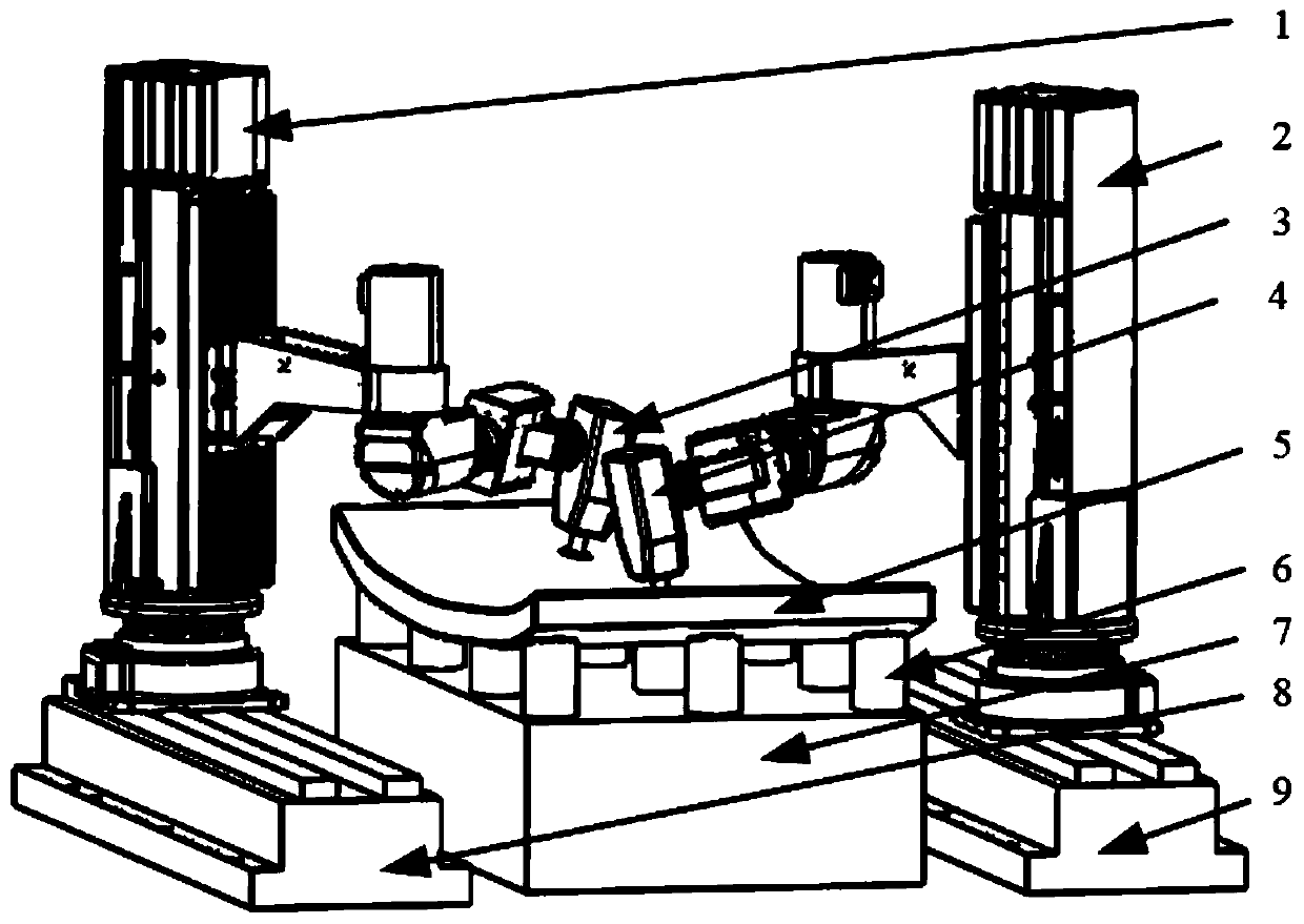
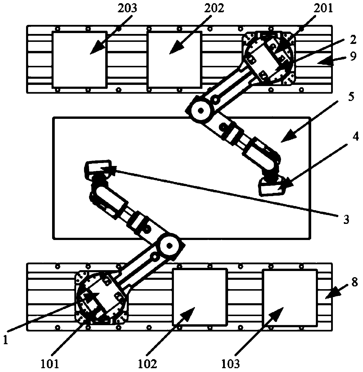
[0068] Firstly, the layout of multiple robots is determined according to the size of the optical element and the processing range of a single robot. The optical element in the specific embodiment 1 can realize the entire optical element 5 by changing the position of the robot on the corresponding slide rail among the two robots. Surface coverage. The first robot 1 and the second robot 2 are symmetrically arranged on both sides of the optical element 5, and a single robot can process half of the optical element. The first robot 1 and the second robot 2 can be positioned on the first robot positioning guide rail 8 and the second robot positioning Slide on the guide rail 9.

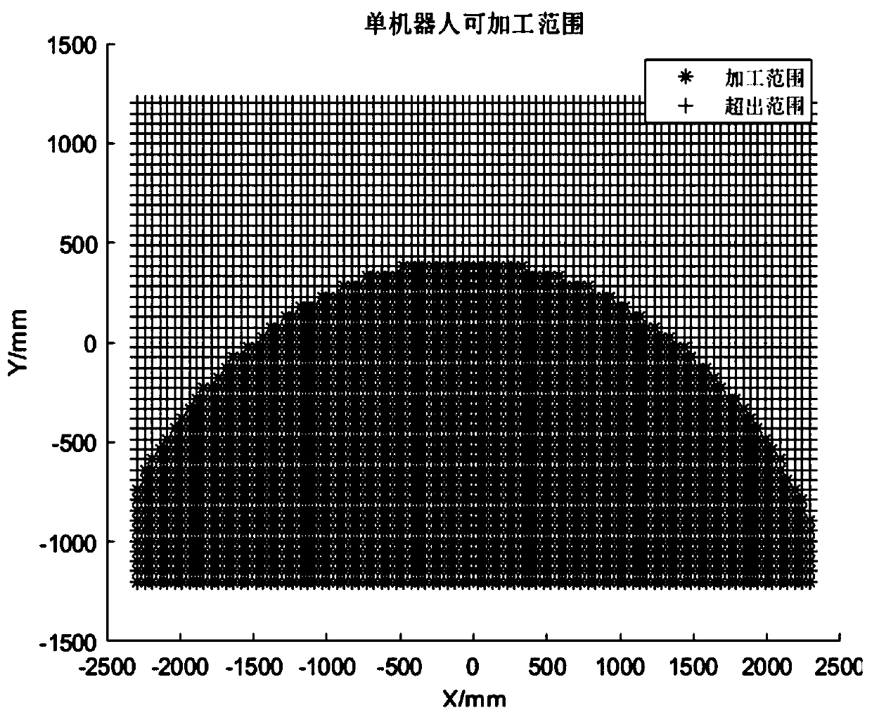
[0069] Further, according to the machinable range of a single robot, calculate and determine the stations required to cover one side of the optical element 5. The double-stat...

specific Embodiment approach 2

[0088] Embodiment 2: This embodiment is mainly aimed at the processing of optical elements with large curvature, and the working mode and processing method of Embodiment 2 are the same as Embodiment 1. Because the curvature of the optical element 5 is relatively large, its grinding process needs to adopt a large-curvature grinding part 334. The grinding square of the large-curvature grinding part 334 is small and the grinding square of the curvature grinding part 335 is small. Under the deformation of the flexible layer 332 of the grinding disc, It can better adapt to large curvature changes on the surface of the element, and has a better fit with the surface of the optical element 5 .

[0089] The used polishing liquid is supplied to the polishing pad 3312 of the recovery tool head module and replaced with a thicker polishing pad, so as to adapt to the curvature change of the large curvature optical element 5 .

[0090] The magnetorheological polishing tool head module adopte...


PUM


Abstract

The invention discloses a multi-robot precision machining system and a method for a large-aperture integral optical element. The multi-robot precision machining system comprises a robot machining system part and a modular machining tool, the modular machining tool comprises a grinding disk machining module, a polishing fluid supply recycling tool head module and a magnetorheological polishing toolhead module. The multi-robot precision machining system and method adopts a flexible intelligent robot with the low cost for machining, by means of multi-robot collaborative machining, machining of large-aperture integrated optical elements with various curvature is realized, meanwhile, the manufacturing efficiency of the optical elements is greatly improved, and a highly integrated modular chemical tool head enables the machining system to be able to conduct grinding modification, polishing modification and precision polishing modification on the large-aperture integral optical elements. Thesystem completes the whole optical machining process, the manufacturing cost of the large-aperture optical elements is greatly saved, and the cycle of the large-aperture optical elements is greatly shortened.

Description

technical field [0001] The invention relates to the technical field of optical element processing, in particular to a multi-robot precision machining system and method for large-diameter integral optical elements. Background technique [0002] With the development of science and technology, the deepening of scientific research on astronomical observation and exploration of the universe, the requirements for the performance of the optical system used are getting higher and higher. It is required to improve the imaging resolution and light collection ability to improve the observation ability, and the increase A large optical aperture is an effective way to improve imaging resolution and light collection ability, so the size of the primary mirror in the astronomical observation system is getting larger and larger. For example, the size of the primary mirror of the European Extremely Large Telescope (E-ELT) reaches 39m, composed of 798 pieces of 1.4m hexagonal sub-mirrors. Simi...

Claims


Application Information

Patent Timeline
IPC IPC(8): B24B13/00B24B37/005B24B37/11B24B37/27
CPCB24B13/00B24B37/005B24B37/11B24B37/27
Inventor 辛强刘海涛万勇建吴介立张勇周敏陈大军唐林刘德平王代路
Owner INST OF OPTICS & ELECTRONICS - CHINESE ACAD OF SCI
Why Eureka
Try Eureka