
Urine water diverter and urine separation and collection device comprising same

A collection device and shunt technology, applied in the field of liquid separation, can solve the problems of increasing urine moisture, failing to collect high-purity urine, urine loss environment, etc., avoiding the loss of urine, simplifying the overall structure, and incapacitating The effect of draining

Pending Publication Date: 2020-02-14
CHANGSHA UNIVERSITY OF SCIENCE AND TECHNOLOGY +1
View PDF3 Cites 2 Cited by
  • Summary
  • Abstract
  • Description
  • Claims
  • Application Information

AI Technical Summary

Problems solved by technology

[0007] Chinese patent CN103074930B discloses a urine separation and collection device. The core components of the device are two funnels. The small flow of urine collected through the "bundle funnel" will definitely fall into the "collection funnel" below it. However, continuous The large flow of flushing water for a long time will also be quickly poured into the collection funnel, which makes the device only able to collect urine with a high water content
The deficiencies of this device are: 1) the default state of the urinal is that the two switches are in the off state, and the low-lying parts of the two S-shaped elbows are full of water. When urinating, the urine pushes these water storages into the urine collection bucket, 2) When flushing after urinating, the first delay switch triggers the second delay switch to be turned on simultaneously, and the tap water pushes the retained urine in these two places into the sewer, resulting in the loss of urine and environmental pollution. 3) During the flushing process, the two switches are required to be turned on at the same time, but the switch 2 is turned off 3 seconds later than the first. , in practice, this is difficult to operate. Usually, when the switch 1 is turned off, the time it takes to drain the remaining water in the urinal has a certain relationship with the pressure of the tap water and the structure of the toilet. Generally speaking, this time Much longer than 3 seconds, the flow of residual water in the pool should not be underestimated. The residual water is likely to fill the low-lying parts of the two elbows and pour it into the urine collection bucket, which further increases the moisture in the urine; 4) During the flushing process, When boiling water, the first delay switch triggers the second delay switch to be turned on at the same time, and the switch 2 needs to be turned off 3 seconds later than the first when it is turned off; this "linkage" operation, regardless of mechanical transmission devices such as gears, connecting rods, or hydraulic equipment, "Mechanical triggering"; or the use of inductive time-delay electromagnetic valves, using the human sensor to send electrical signals after urination and the person has left the urinal, to perform "inductive triggering"; all of which make the structure of the device very complicated. Increased product manufacturing, use and maintenance costs
[0009] Chinese patent CN107740481B discloses a urinal device, which overcomes the shortcomings of the above two solutions that can only collect low-purity urine, but still has a rather complicated structure, especially changing the habit of people going to the toilet, because in the initial state, The "toggle block" is at the top of the operation tank. When urinating, it must be moved down to the bottom of the operation tank to collect urine; when flushing, the "toggle block" must be moved up to the operation At the top of the tank, press the "press block" to turn on the flush switch to complete the flushing operation of the toilet
The devices in the prior art have the following deficiencies: some devices have changed the habit of people going to the toilet, some devices cannot collect high-purity urine, some devices need to be powered on and consume energy, and some devices have complex structures

Method used


Image

  • Urine water diverter and urine separation and collection device comprising same
  • Urine water diverter and urine separation and collection device comprising same
  • Urine water diverter and urine separation and collection device comprising same

Examples


Embodiment 1

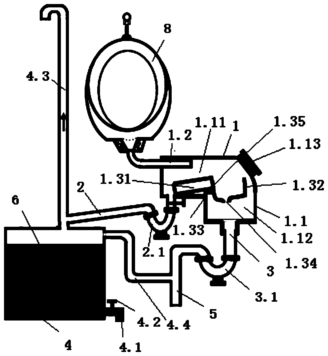
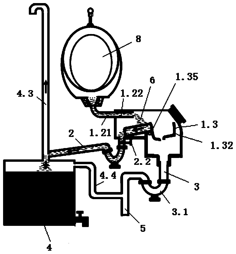
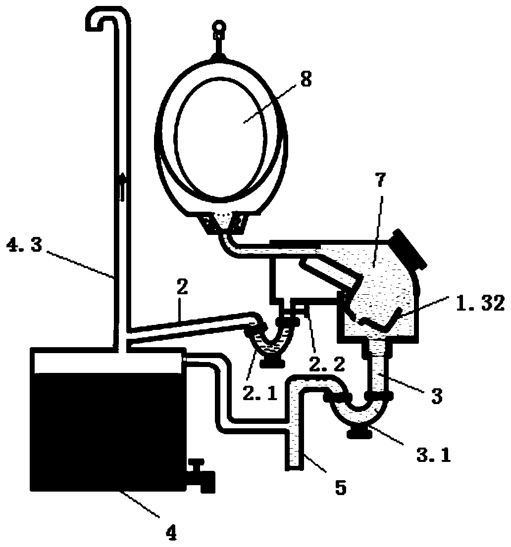
[0040] see Figure 1-Figure 3 , a urine separation and collection device, comprising a urine water diverter 1, a urine channel 2, a water flow channel 3 and a urine collection container 4, the details are as follows:

[0041] The urine diverter 1 includes a housing 1.1, a liquid guiding part 1.2 and a lever member 1.3; the inner cavity of the housing 1.1 includes a urination cavity 1.11 and a drainage cavity 1.12; the lower end of the urination cavity 1.11 is provided with a urination port; One end of the urine channel 2 containing the liquid trap 2.1 communicates with the urination port, and the other end communicates with the urine collection container 4, and a valve A (marked as 2.2) is provided between the liquid trap 2.1 and the urination port, here also The odor-proof core can be directly used without a liquid trap, and the odor-proof core is arranged at the urination opening; the lower end of the drainage chamber 1.12 is provided with a drain port, and one end of the wa...

Embodiment 2

[0052] See details Figure 4-Figure 5 (Illustrating the internal structure of the urine diverter of embodiment 2), embodiment 2 differs from embodiment 1 in that:

[0053] The outlet pipe section 1.22 is a three-way pipe composed of a left inlet section 1.221, a lower outlet section 1.222 and a right outlet section 1.223, and the three-way pipe is arranged at the upper left end of the inner cavity of the housing; The left inlet section 1.221 communicates through the shell wall of the housing 1.1, and the lower inner wall of the left inlet section 1.221 is higher than the lower inner wall of the right outlet section 1.223.

[0054] The ladle handle part 1.31 is a rod-shaped, groove-shaped or plate-shaped ladle handle, and the ladle handle is provided with a spherical, spherical, conical or conical blocking block 1.36, and the blocking block is made of soft material, hard material or soft material. Material combined with hard material, when flushing water is poured into the lad...

Embodiment 3

[0060] Embodiment 3 differs from Embodiment 2 in that: see Figure 6 The liquid guiding part 1.2 includes a split liquid inlet pipe section 1.21 and a liquid outlet pipe section 1.22, the liquid inlet pipe section 1.21 is inserted into the left inlet section 1.221, and the lower inner wall of the outlet end of the liquid inlet pipe section 1.21 is higher than the liquid outlet The lower inner wall of the right outlet section 1.223 in the pipe section 1.22.

[0061] The principle of embodiment 3 is the same as embodiment 2.


PUM


Abstract

The present invention provides a urine water diverter. The urine water diverter comprises a shell, a liquid guide part and a gourd ladle-shaped lever component, wherein the lower end of the shell is provided with a urine discharge port and a water drainage port; the middle section of an inner cavity of the shell is provided with the lever component; the upper section of the shell is provided withthe liquid guide part which penetrates through the shell wall; the upper port of the liquid guide part is communicated with a toilet; and urine and flushing water at different flow rates can be automatically shunted through the ingenious cooperation of the liquid guide part and the lever component. By applying the urine water diverter, the urine discharge port is communicated with a urine collection container through a urine channel, and the water drainage port is communicated with a sewer through a water flow channel, so that a complete urine separation and collection device can be constructed. The device is characterized in that the device is simple in structure, does not consume energy, does not change toilet habits of people, can be installed in a public toilet or a farmer house, can even be applied to a user without tap water supply, can collect high-purity urine for refining urokinase by a pharmaceutical factory, and is used for extracting valuable phosphorus from a chemical plant for farmer planting and soil fertilization.

Description

technical field [0001] The invention relates to the technical field of liquid separation, in particular to a urine diverter and a urine separation and collection device containing the diverter. Background technique [0002] In cities, urine is directly discharged into the sewer through the toilet, and then flows into the sewage treatment plant remotely. This terminal treatment technology for centralized discharge of domestic sewage has complex processes and high treatment costs, and completely blocks nitrogen, phosphorus, potassium, etc. in feces and urine. The ecological way of returning nutrients to the land is increasingly being questioned. [0003] In rural areas, some farmers directly pull urine into urine buckets or simple latrines to collect fertilizers, causing mosquitoes to infeste and stink; while other farmers use water flushers to pour urine into septic tanks and then flow into the ground. It pollutes the groundwater quality in rural areas and wastes a lot of ec...

Claims


Application Information

Patent Timeline
IPC IPC(8): E03D9/00E03C1/12E03C1/122
CPCE03D9/00E03C1/12E03C1/122
Inventor 厉江帆厉韧张振华刘其城肖伏良史向华袁剑辉丁开河鲁耿彪
Owner CHANGSHA UNIVERSITY OF SCIENCE AND TECHNOLOGY
Learn More