
Stirling engine and heat exchange method thereof

A Stirling engine and thermal cavity technology, applied in the direction of machines/engines, hot gas variable displacement engine devices, mechanical equipment, etc., can solve the problems that cannot be realized at the same time, the problems of heaters and regenerators cannot be solved, and cannot be satisfied at the same time and other issues, to achieve the effect of good thermal response

Active Publication Date: 2020-02-21
BEIJING FUDIAN ENG TECH CO LTD
View PDF4 Cites 3 Cited by
  • Summary
  • Abstract
  • Description
  • Claims
  • Application Information

AI Technical Summary

Problems solved by technology

Obviously, the above requirements not only cannot be realized simultaneously in practice, but also contradict each other in design theory and cannot be satisfied at the same time, so the regenerator is another key element restricting the performance of the Stirling engine
[0012] For more than 200 years since 1816, the Stirling engine has experienced the unremitting efforts of countless experts, but it has not solved the heater and regenerator problems that restrict the development of the Stirling engine, and has not yet achieved a major application breakthrough. The main performance When the engine power ≦ 100KW, the comprehensive thermal efficiency ≤ 35%

Method used


Image

  • Stirling engine and heat exchange method thereof
  • Stirling engine and heat exchange method thereof
  • Stirling engine and heat exchange method thereof

Examples


Embodiment Construction

[0103] Example embodiments will now be described more fully with reference to the accompanying drawings; however, example embodiments may be embodied in various forms and should not be construed as limited to only those set forth herein; rather, these are provided so that the present invention It will be thorough and complete and will fully convey the concept of the example embodiments to those skilled in the art. The same reference numerals in the drawings denote the same or similar structures, and thus their detailed descriptions will be omitted.

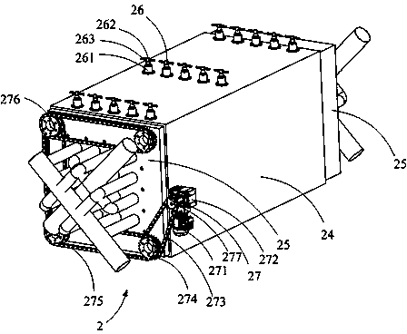
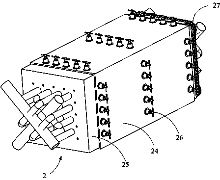
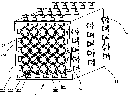
[0104] figure 1 A Stirling engine 1 is shown comprising an expansion cylinder 3, a compression cylinder 4, a heat exchanger 2, an air cooler 5, a crankshaft (not shown), a combustion furnace 6 and a drum Wind compressor7. The expansion cylinder 3 and the compression cylinder 4 communicate with each other, and the working medium is loaded in the cylinder. The working medium is gas. The heat exchanger 2 and the air cooler 5 are ...


PUM


Abstract

The invention provides a Stirling engine and a heat exchange method thereof. The Stirling engine comprises a crank shaft, expansion cylinders, compression cylinders, a heat exchanger and an air cooler. The heat exchanger comprises a heat cavity, multiple work medium cavities and multiple rotation columns. Cold and hot work mediums are in mutual countercurrent flow, and the heat cavity and the workmedium cavities at least share the outer side wall of the same rotation column as the respective inner wall. The air cooler comprises a first cooling channel. The expansion first cylinder and the first compression cylinder can be alternately compressed when the crank shaft rotates. Working work mediums perform surface heat exchange in the work medium cavities and do not need to be filled with heat retainer materials, and a heat storage and release function of a heat regenerator can be achieved. The situation is avoided that due to too small gaps of heat retainers, the flow resistance of the work mediums is large, and multiple problems are caused. High-temperature hot air energy is sufficiently used through countercurrent flow heat exchange. The heat exchange method of the Stirling engineis suitable for heat exchange of the Stirling engine under a high-temperature environment and achieves high comprehensive heat efficiency.

Description

technical field [0001] The invention relates to the field of high-temperature heat exchange in the heat transfer aspect of special engineering, in particular to a Stirling engine and a heat exchange method thereof. Background technique [0002] The Stirling engine is a closed-cycle engine heated by external combustion, which has five outstanding advantages: [0003] ①. The wide spectrum of fuel, because it is heated by external combustion, it can adapt to various gases, liquids, solid fuels, solar energy and waste heat. [0004] ②.Theoretical cycle thermal efficiency is high, which is closest to the thermal efficiency of Carnot cycle. [0005] ③. Simple structure, no intake and exhaust valve system. [0006] ④. Low noise, neither the deflagration noise of the internal combustion engine nor the screaming noise of the steam turbine airflow. [0007] ⑤.Because it belongs to the closed cycle working fluid, it can run under pressure, which can effectively reduce the volume of ...

Claims


Application Information

Patent Timeline
Patent Type & Authority Applications(China)
IPC IPC(8): F02G1/044F02G1/055F02G1/057
CPCF02G1/044F02G1/055F02G1/057
Inventor 张孔明张立
Owner BEIJING FUDIAN ENG TECH CO LTD
Learn More