Organic compound based on triazine and anthrone structure, and applications thereof

An organic compound and anthrone technology, applied to organic electroluminescent devices, in the field of organic compounds based on triazine and anthrone structures, can solve the problems that affect the OLED radiation spectrum angle distribution, complex manufacturing process, etc.

Active Publication Date: 2020-03-13
JIANGSU SUNERA TECH CO LTD
View PDF10 Cites 6 Cited by
  • Summary
  • Abstract
  • Description
  • Claims
  • Application Information

AI Technical Summary

Problems solved by technology

The first two structures will affect the angular distribution of the radiation spectrum of the OLED. The third structure is complicated to manufacture, and t

Method used

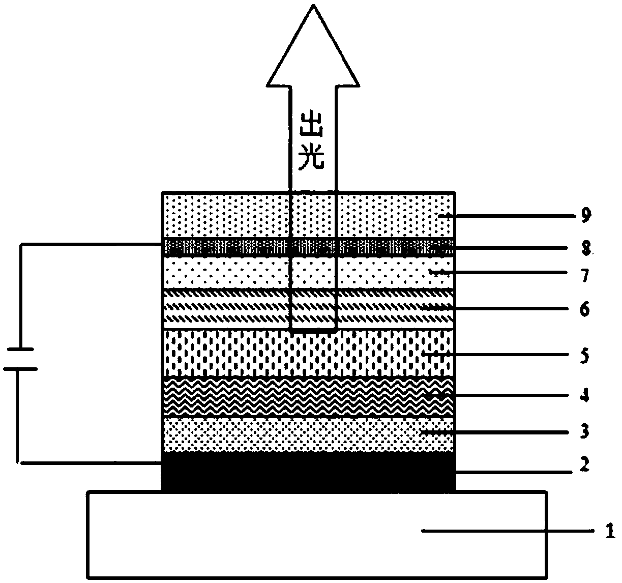
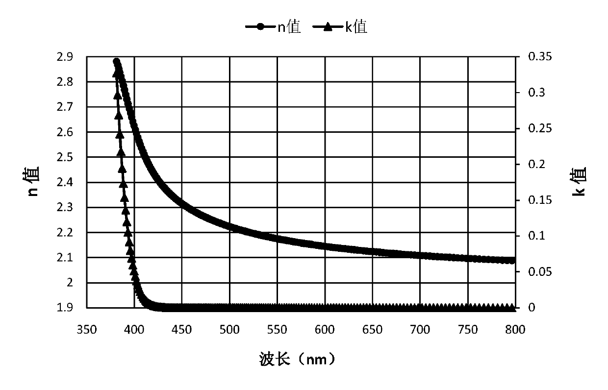
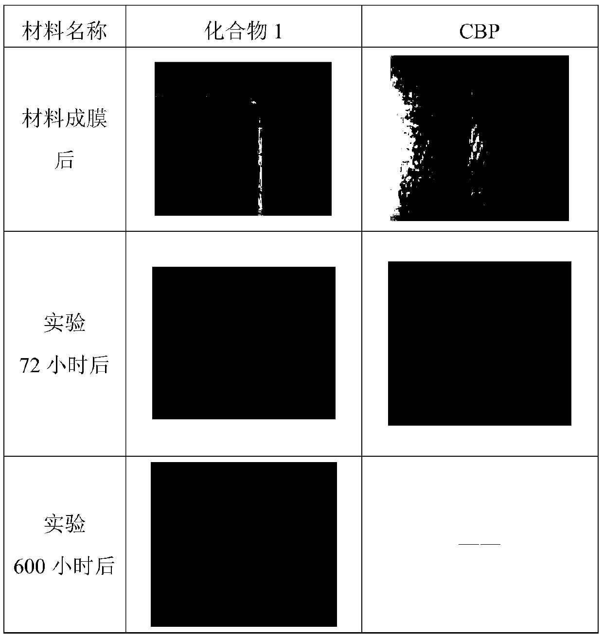

Image

  • Organic compound based on triazine and anthrone structure, and applications thereof
  • Organic compound based on triazine and anthrone structure, and applications thereof
  • Organic compound based on triazine and anthrone structure, and applications thereof

Examples


Embodiment 1

[0110] Embodiment 1: the synthesis of intermediate A

[0111] When Ar 1 is not a single bond; or Ar1 is a single bond, R 1 When connecting with the mother nucleus triazine as C-C:

[0112]

[0113] (1) Under a nitrogen atmosphere, weigh the raw material I and dissolve it in tetrahydrofuran (THF), then add bis(pinacolyl)diboron, (1,1'-bis(diphenylphosphino)ferrocene)dichloro Palladium (II) and potassium acetate are added, the mixture is stirred, and the mixed solution of the above reactants is heated to reflux at a reaction temperature of 70-90°C for 5-10 hours; dry. Separating and purifying the obtained residue through a silica gel column to obtain intermediate E; the molar ratio of the raw material I to bis(pinacol radical) diboron is 1:1.0~3, Pd(dppf) 2 Cl 2 The molar ratio to raw material I is 0.001-0.04:1, the molar ratio of potassium acetate to raw material I is 1.0-4.0:1, and the ratio of raw material I to THF is 1g:10-30ml.

[0114] (2) Under a nitrogen atmosph...

Embodiment 2

[0154] Embodiment 2: the synthesis of compound 1

[0155]

[0156] In a 250mL three-necked flask, blow nitrogen, add 0.01mol of intermediate A1, 150ml of DMF (N,N-dimethylformamide), 0.03mol of raw material B1, 0.0002mol of palladium acetate, stir, and then add 0.04mol of K 3 PO 4 Aqueous solution, heated to 150°C, refluxed for 24 hours, sampled and plated, the reaction was complete; naturally cooled to room temperature, extracted with 200mL dichloromethane and 200mL water, separated, took the organic phase and dried it with anhydrous sodium sulfate, filtered, and the filtrate Rotary evaporation and silica gel column purification gave the target product with a HPLC purity of 99.1% and a yield of 56.3%.

[0157] Elemental analysis structure (molecular formula C 53 h 31 N 3 o 4 ): theoretical value C, 82.26; H, 4.04; N, 5.43; 0, 8.27; test value: C, 82.27; ESI-MS(m / z)(M + ): The theoretical value is 773.23, and the measured value is 773.34.

Embodiment 3

[0158] Embodiment 3: the synthesis of compound 2

[0159]

[0160] The preparation method of compound 2 is the same as that of Example 2, except that intermediate A1 is replaced by intermediate A2. Elemental analysis structure (molecular formula C 53 h 31 N 3 o 4 ): theoretical value C, 82.26; H, 4.04; N, 5.43; 0, 8.27; test value: C, 82.24; ESI-MS(m / z)(M + ): The theoretical value is 773.23, and the measured value is 773.32.


PUM


Abstract

The invention relates to an organic compound based on a triazine and anthrone structure, and applications in OLED devices. The compound has high glass transition temperature and high molecular thermalstability, and is low in absorption in the field of visible light and high in refractive index. After the compound is applied to the covering layer (CPL) of an OLED device, the light extraction efficiency of the OLED device can be effectively improved. The compound disclosed by the invention also has a deep HOMO energy level and high electron mobility, can be used as the hole blocking/electron transport layer material of an OLED device, and can effectively block holes or energy from being transmitted from a light emitting layer to one side of an electron layer so as to improve the recombination efficiency of the holes and the electrons in the light emitting layer, so that the light emitting efficiency and the service life of the OLED device are improved.

Description

technical field [0001] The invention relates to the technical field of semiconductors, in particular to an organic compound based on a triazine and anthrone structure and its application in an organic electroluminescence device. Background technique [0002] Organic electroluminescent (OLED: Organic Light Emission Diodes) device technology can be used to manufacture new display products and also can be used to make new lighting products, which is expected to replace the existing liquid crystal display and fluorescent lighting, and has a wide application prospect. The OLED light-emitting device is like a sandwich structure, including electrode material film layers and organic functional materials sandwiched between different electrode film layers. Various functional materials are superimposed on each other according to the application to form an OLED light-emitting device. OLED light-emitting devices are current devices. When a voltage is applied to the electrodes at both end...

Claims


Application Information

Patent Timeline
IPC IPC(8): C07D405/14C07D409/14C07D421/14C07D251/24C07D401/14C07D405/04C07D405/10C07D413/14C07D417/14C07D403/04C07D403/10C09K11/06H01L51/50H01L51/52H01L51/54
CPCC07D405/14C07D409/14C07D421/14C07D251/24C07D401/14C07D405/04C07D405/10C07D413/14C07D417/14C07D403/04C07D403/10C09K11/06C09K2211/1007C09K2211/1011C09K2211/1014C09K2211/1029C09K2211/1033C09K2211/1037C09K2211/1044C09K2211/1059C09K2211/1088C09K2211/1092C09K2211/1096H10K85/626H10K85/636H10K85/633H10K85/615H10K85/654H10K85/6576H10K85/6574H10K85/6572H10K85/657H10K50/16H10K50/18H10K50/85
Inventor 李崇蔡啸唐丹丹张兆超
Owner JIANGSU SUNERA TECH CO LTD
Why Eureka
Try Eureka