Eureka AIR delivers breakthrough ideas for toughest innovation challenges, trusted by R&D personnel around the world.

Single-stage, multi-stage and variable-stage cyclone air flotation oily sewage treatment device

A swirling air flotation and treatment device technology, which is applied in the direction of flotation water/sewage treatment, multi-stage water treatment, water/sludge/sewage treatment, etc. Not suitable for problems such as offshore platforms, achieving convenient and stable circulation channels, avoiding repeated processing, and compact structure

Active Publication Date: 2022-02-08
CHINA UNIV OF PETROLEUM (EAST CHINA)
View PDF8 Cites 2 Cited by
  • Summary
  • Abstract
  • Description
  • Claims
  • Application Information

AI Technical Summary

Problems solved by technology

[0004] Chinese invention patent CN109052558A discloses a cyclone air flotation separation device, which combines the filtration process and adds filter material at the bottom of the separator, which can effectively reduce the oil concentration at the water outlet. However, due to the lack of backwashing process, the equipment needs to be stopped for a certain period of time. It is difficult to meet the requirements of long-term stable operation on site; Chinese invention patent CN106587243A discloses a cyclone-air-flotation integrated device, which performs a cyclone separation and two air-flotation separations on the sewage, and the separation effect is better. However, the structure of the equipment is complicated, there is a gas phase space on the top of the separator, and the liquid surface is easy to shake, which is not suitable for offshore platforms; Chinese invention patent CN106865673A discloses a secondary cyclone air flotation oily sewage treatment device, which weakens the cyclone intensity by increasing the inner cylinder Attenuation, but because it is a single inlet, the flow field distribution in the separator is uneven, and it is difficult to achieve high-efficiency separation; Chinese invention patent CN103303992A discloses a cyclone air flotation separation device for oily sewage. Although the device has two-stage separation, the two-stage device Simple series connection, without integrated prying, it is difficult to meet the requirements of compactness and high efficiency

Method used


Image

  • Single-stage, multi-stage and variable-stage cyclone air flotation oily sewage treatment device
  • Single-stage, multi-stage and variable-stage cyclone air flotation oily sewage treatment device
  • Single-stage, multi-stage and variable-stage cyclone air flotation oily sewage treatment device

Examples


Embodiment 1

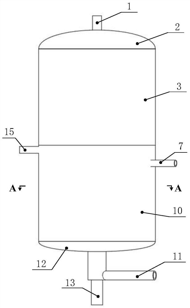
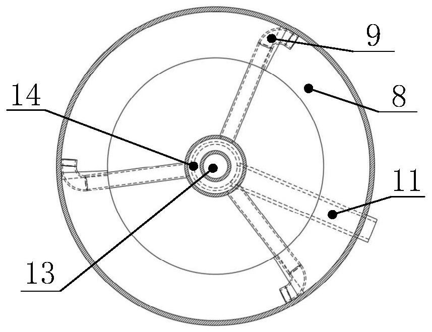
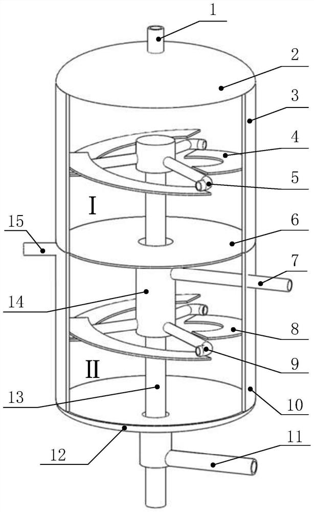
[0034] see figure 1 , figure 2 , image 3 , a two-stage cyclone air flotation oily sewage treatment device is characterized in that it includes an outer shell part composed of a first-stage cylindrical shell 3, a second-stage cylindrical shell 10, an upper seal head 2, and a lower seal head 12; it consists of a Level overflow pipe 1, secondary overflow pipe 15, secondary return pipe 7, underflow pipe 11, central standpipe 13 constitute the inlet and outlet pipeline part; Deflector 4, secondary deflector 8, secondary annular channel 14 and primary treated water collecting plate 6; wherein, the primary overflow pipe 1 is located at the top center of the upper head 2, and the secondary The primary overflow pipe 15 is located at the top position of the secondary cylinder body 10, and the secondary overflow pipe 15 is perpendicular to the central axis of the secondary cylinder body 10; the bottom flow pipe 11 is located on the lower head 12; the secondary return pipe 7 vertical...

Embodiment 2

[0043] see Figure 4 , a single-stage cyclone air flotation oily sewage treatment device, compared with the two-stage cyclone air flotation oily sewage treatment device in Example 1, it is equivalent to dismantling the primary treatment water collecting plate 6, the secondary return pipe 7, the secondary Level baffle 8, level 2 water distribution pipe 9, level 2 barrel 10, level 2 annular channel 14, level 2 overflow pipe 15.

[0044] The working process of the present invention is described as follows:

[0045] Uniformly mixed with gas to form oily sewage dissolved with microbubbles through the central standpipe 13, and tangentially flow out from the primary water distribution pipe 5 to form a swirling flow. It is advisable to control the centrifugal acceleration at the outlet of the water distribution pipe 5 at 15g~25g. Because the density of air bubbles and oil droplets is lower than that of water, they move centripetally and directionally in the swirl field, collide and c...

Embodiment 3

[0047] see Figure 5 , a three-stage cyclone air flotation oily sewage treatment device is on the basis of embodiment 1, adding a three-stage return pipe 16, a three-stage deflector 17, a three-stage water distribution pipe 18, a three-stage cylinder body 19, and a three-stage Annular channel 20 , tertiary overflow pipe 21 , and secondary treated water collecting plate 22 . The characteristics of the components in the third-level separation zone III are the same as those of the corresponding components in the secondary separation zone II.

[0048] The working process of the present invention is described as follows:

[0049] On the basis of Examples 1 and 2, the purified water after the secondary separation II flows to the secondary treated water collecting plate 22 below, and then flows to the tertiary separation through the tertiary annular channel 20 in the center of the secondary treated water collecting plate 22 Zone III. When the secondary purified water passes throug...


PUM


Abstract

Single-stage, multi-stage and variable-stage cyclone air flotation oily sewage treatment devices, including the external shell composed of cylindrical cylinders and upper and lower heads; overflow pipes, return pipes, and underflow pipes at all levels 1. The inlet and outlet pipeline part composed of central standpipe; the internal structure composed of water distribution pipes at all levels, deflectors at all levels, annular channel and treated water collection plate. The primary overflow pipe is located on the top of the upper head, and the other overflow pipes are located on the upper side of the shells at all levels; the bottom flow pipe is located at the lower head; the return pipes of all levels pass through the shells of all levels and communicate with the annular passages of all levels; the central standpipe It is located on the axis of the cylinder and passes through the lower head, the annular passage and the cylinders at all levels; the first-level water distribution pipe is located at the top of the central riser, and the others are located at the bottom of the annular passage; the deflectors at all levels are spirally inclined and fixed in the cylinders at all levels Wall; treatment water collection plate is located between the two cylinders. The invention has the advantages of compact structure, simple operation, single multi-stage design to meet the requirements of different effluent water quality and treatment capacity, wide applicability and good oil removal effect.

Description

technical field [0001] The invention relates to a single-stage, multi-stage and variable-stage cyclone air flotation oily sewage treatment device. The device couples the traditional cyclone separation technology with the air flotation technology, and is suitable for simple process requirements and limited space and site , Oily sewage treatment occasions with high requirements for drainage water quality, belonging to the technical field of multiphase separation of oil and gas gathering and transportation systems. Background technique [0002] In the late stage of oilfield development, the water content of the produced fluid continues to rise, and the amount of oily sewage treatment increases greatly; in the tertiary oil recovery, the polymer flooding produced fluid is seriously emulsified and difficult to purify; Limited, strict requirements on equipment processing efficiency and floor space. [0003] At present, the commonly used sewage treatment technologies are as follows...

Claims


Application Information

Patent Timeline
Patent Type & Authority Patents(China)
IPC IPC(8): C02F1/40C02F1/24C02F101/32C02F103/10
CPCC02F1/40C02F1/24C02F2101/32C02F2103/10C02F2301/08
Inventor 罗小明刘萌何利民吕宇玲
Owner CHINA UNIV OF PETROLEUM (EAST CHINA)
Why Eureka
Eureka Blog
Learn More