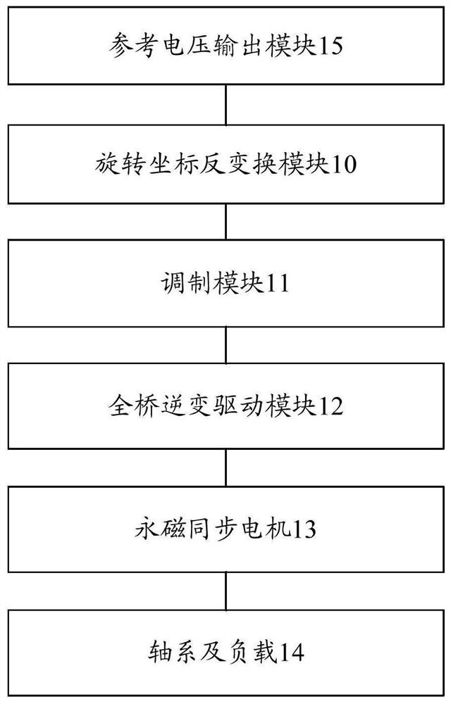
A Laser Terminal Coarse Pointing Mechanism Working Mode Recognition and Position Control System
A technology of pointing mechanism and working mode, which is applied in the field of satellite laser communication, can solve problems such as rapid system response without overshoot, inappropriate parameter adjustment, controller parameter adjustment, etc., to achieve dynamic and steady-state performance Index requirements, improve drive control performance, and achieve simple effects
- Summary
- Abstract
- Description
- Claims
- Application Information
AI Technical Summary
Problems solved by technology
Method used
Image
Examples
Embodiment 1
[0060] The embodiment of the invention discloses a laser terminal coarse pointing mechanism working mode recognition and position control system, which not only has a simple structure and convenient parameter adjustment, but also can meet the real-time control requirements of current processors. The servo control of the coarse pointing mechanism of the laser terminal adopts the three-loop control of the position loop, the velocity loop and the current loop. For the convenience of analysis, the velocity loop and the current loop shown in the embodiment of the present invention both adopt the traditional PI control structure. The invention has been successfully applied to a certain high-orbit satellite laser communication subsystem, and achieved better control effects.
[0061] For the convenience of analysis, considering that the response of the current loop and the speed loop are much faster than the response of the position loop, that is, the cut-off frequency of the position ...
Embodiment 2
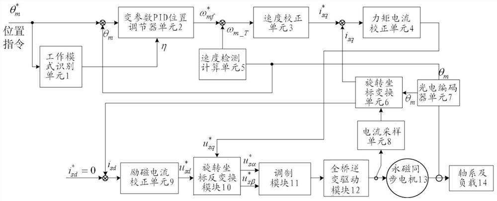
[0076] In an embodiment of the present invention, the reference voltage output module 15 may specifically include: a d-axis reference voltage output sub-module for generating a d-axis reference voltage of the motor of the coarse pointing mechanism and Output: The q-axis reference voltage output sub-module is used to generate and output the q-axis reference voltage of the motor of the coarse pointing mechanism according to the position command and the motor current of the coarse pointing mechanism.
[0077] In a preferred embodiment of the present invention, as image 3 , the d-axis reference voltage output sub-module may specifically include:
[0078] The current sampling unit 8 is used to detect and output the motor current of the coarse pointing mechanism.
[0079] The rotating coordinate transformation unit 6 is used for performing vector calculation on the motor current of the coarse pointing mechanism output by the current sampling unit 8, and outputting the current comp...
Embodiment 3
[0096] In this embodiment, according to the identified working mode, different PID control parameters are selected according to different dynamic index requirements, and when it is necessary to realize position setting without overshoot index, a group of control parameters with lower dynamic performance is selected; When it is necessary to achieve a lower tracking error, a set of control parameters with lower dynamic performance is selected to achieve the purpose of position control variable parameter PID control. The following is an analysis of the position servo system of the coarse pointing mechanism. Such as image 3 , The coarse pointing mechanism of the laser terminal is directly driven by a permanent magnet synchronous motor, and high-precision control needs to achieve closed-loop control. In the closed-loop control of the permanent magnet synchronous motor, it is necessary to complete the high-speed and high-precision sampling of the angle sensor and the winding curre...
PUM
 Abstract
Description
Claims
Application Information
 - R&D
- Intellectual Property
- Life Sciences
- Materials
- Tech Scout
- Unparalleled Data Quality
- Higher Quality Content
- 60% Fewer Hallucinations
Browse by: Latest US Patents, China's latest patents, Technical Efficacy Thesaurus, Application Domain, Technology Topic, Popular Technical Reports.
© 2025 PatSnap. All rights reserved.Legal|Privacy policy|Modern Slavery Act Transparency Statement|Sitemap|About US| Contact US: help@patsnap.com


