Sub-threshold digital circuit time sequence optimization method and system

A digital circuit, sub-threshold technology, applied in the direction of electrical digital data processing, special data processing applications, instruments, etc., can solve the problems of reducing unit performance, slow device optimization speed, increasing area, etc., to improve circuit performance and realize timing Optimize and reduce the effect of delay time

Pending Publication Date: 2020-04-03
INST OF MICROELECTRONICS CHINESE ACAD OF SCI
View PDF0 Cites 0 Cited by
  • Summary
  • Abstract
  • Description
  • Claims
  • Application Information

AI Technical Summary

Problems solved by technology

It is precisely because the device works in the sub-threshold region that the current and voltage of the device have an exponential relationship, and the change in the size of the device will lead to obvious changes in current and parasitic capacitance, which will significantly change the electrical performance of the circuit.
In addition, circuit performance fluctuates greatly with PVT (Process-Voltage-Temperature, process-temperature-voltage) deviation. In order to make the designed sub-threshold digital circuit have high robustness, the design optimization process of sub-threshold digital circuit Statistical analysis and optimization of PVT deviation need to be considered in the process, which will exponentially increase the complexity of device size optimization for sub-threshold digital circuits, making the process of device optimization speed extremely slow
[0003] At present, with the increase in the scale of sub-threshold digital circuits, the combination of statistical analysis and optimization of PVT deviations

Method used


Image

  • Sub-threshold digital circuit time sequence optimization method and system
  • Sub-threshold digital circuit time sequence optimization method and system
  • Sub-threshold digital circuit time sequence optimization method and system

Examples


Embodiment Construction

[0047] The following will clearly and completely describe the technical solutions in the embodiments of the present invention with reference to the accompanying drawings in the embodiments of the present invention. Obviously, the described embodiments are only some, not all, embodiments of the present invention. Based on the embodiments of the present invention, all other embodiments obtained by persons of ordinary skill in the art without making creative efforts belong to the protection scope of the present invention.

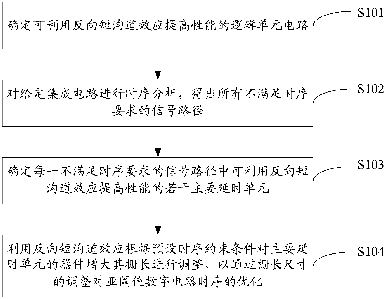
[0048] Such as figure 1 As shown, the embodiment of the present invention provides a sub-threshold digital circuit timing optimization method, the method may specifically include the following steps:

[0049] S101. Determine a logic unit circuit that can improve performance by utilizing the reverse short channel effect.

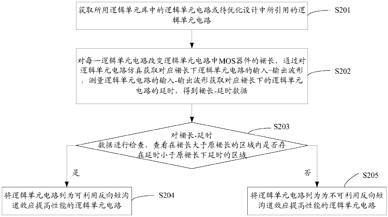
[0050] In the embodiment of the present invention, such as figure 2 As shown, it is a specific implementation of the above step S101. Spe...


PUM


Abstract

The invention discloses a sub-threshold digital circuit time sequence optimization method and system. The method comprises the following steps: firstly, determining a logic unit circuit capable of improving the performance by utilizing a reverse short channel effect; performing time sequence analysis on a given integrated circuit to obtain all signal paths which do not meet the time sequence requirement; then determining a plurality of main delay units capable of improving the performance by utilizing a reverse short channel effect in each signal path which does not meet the time sequence requirement; and finally, increasing the gate length of the device of the main time delay unit by using a reverse short channel effect according to a preset time sequence constraint condition to carry outadjustment, and adjusting the gate length size to optimize the time sequence of the sub-threshold digital circuit. According to the invention, the gate length of a device of a main time delay unit isincreased by using a reverse short channel effect, so that time sequence optimization is realized, the circuit performance of a sub-threshold digital circuit is improved, and the time delay time of the unit is reduced; and meanwhile, the consistency of unit delay is improved by increasing the area, so that the robustness of the circuit is enhanced.

Description

technical field [0001] The invention relates to the technical field of circuit timing optimization, in particular to a sub-threshold digital circuit timing optimization method and system. Background technique [0002] Subthreshold digital circuits refer to digital logic circuits whose operating voltage is lower than the threshold voltage of transistor devices. Since the circuit operates in the subthreshold region, the dynamic power consumption and static power consumption of the circuit can be greatly reduced. It is precisely because the device works in the sub-threshold region that the current and voltage of the device have an exponential relationship, and changes in the size of the device will lead to significant changes in current and parasitic capacitance, thereby significantly changing the electrical performance of the circuit. In addition, circuit performance fluctuates greatly with PVT (Process-Voltage-Temperature, process-temperature-voltage) deviation. In order to m...

Claims


Application Information

Patent Timeline
IPC IPC(8): G06F30/3312
Inventor 吴玉平陈岚张学连
Owner INST OF MICROELECTRONICS CHINESE ACAD OF SCI
Why Eureka
Try Eureka