
Semiconductor interconnection structure and preparation method thereof

An interconnection structure and semiconductor technology, applied in semiconductor/solid-state device manufacturing, semiconductor devices, semiconductor/solid-state device components, etc., can solve problems such as large resistance value of filling metal layer, reduction of driving resistance, and reduction of device driving resistance, etc. To achieve the best coverage of the ladder, slow down the top obstacles, and reduce the effect of resistance value

Pending Publication Date: 2020-04-03
CHANGXIN MEMORY TECH INC
View PDF0 Cites 1 Cited by
  • Summary
  • Abstract
  • Description
  • Claims
  • Application Information

AI Technical Summary

Problems solved by technology

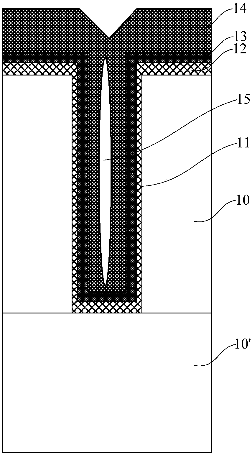
[0003] However, as the miniaturization of devices continues to deepen, the size of the semiconductor interconnection structure becomes smaller and smaller. The tungsten metal layer is formed by filling the contact hole 11 with a high aspect ratio in one step using the existing chemical vapor deposition process. 14, it is easy to form a hole 15 in the tungsten metal layer 14 in the contact hole 11, the existence of the hole 15 will cause electromigration problems in the subsequent copper process, and will make the metal layer filled in the contact hole The resistance value is large, which leads to a decrease in the reliability of the semiconductor device
In addition, when filling the tungsten metal layer 14 in the contact hole 11, a metal wiring layer must be formed to be connected to the tungsten metal layer 14 to reduce the driving resistance of the device, and forming a metal wiring layer will inevitably occupy the The effective area in the dielectric layer 10, so that the effective area in the dielectric layer 10 becomes smaller
[0004] Since copper has a lower resistivity than tungsten, filling copper in the contact hole 11 can reduce the driving resistance of the device without forming an additional metal wiring layer. However, for figure 1 In terms of the contact hole 11, since the top of the contact hole 11 is right-angled (that is, the sidewall of the contact hole 11 is vertically connected to the upper surface of the dielectric layer 10), before electroplating copper, When the barrier layer and the seed layer are formed, an overhang will be generated at the contact hole 11, so that when the filled copper is electroplated, a hole will be generated inside the filled copper, and the edge area of ​​the contact hole 11 will be filled with copper. The thickness is small, which leads to the electrical failure of the device (EM / SM)

Method used


Image

  • Semiconductor interconnection structure and preparation method thereof
  • Semiconductor interconnection structure and preparation method thereof
  • Semiconductor interconnection structure and preparation method thereof

Examples


Embodiment 1

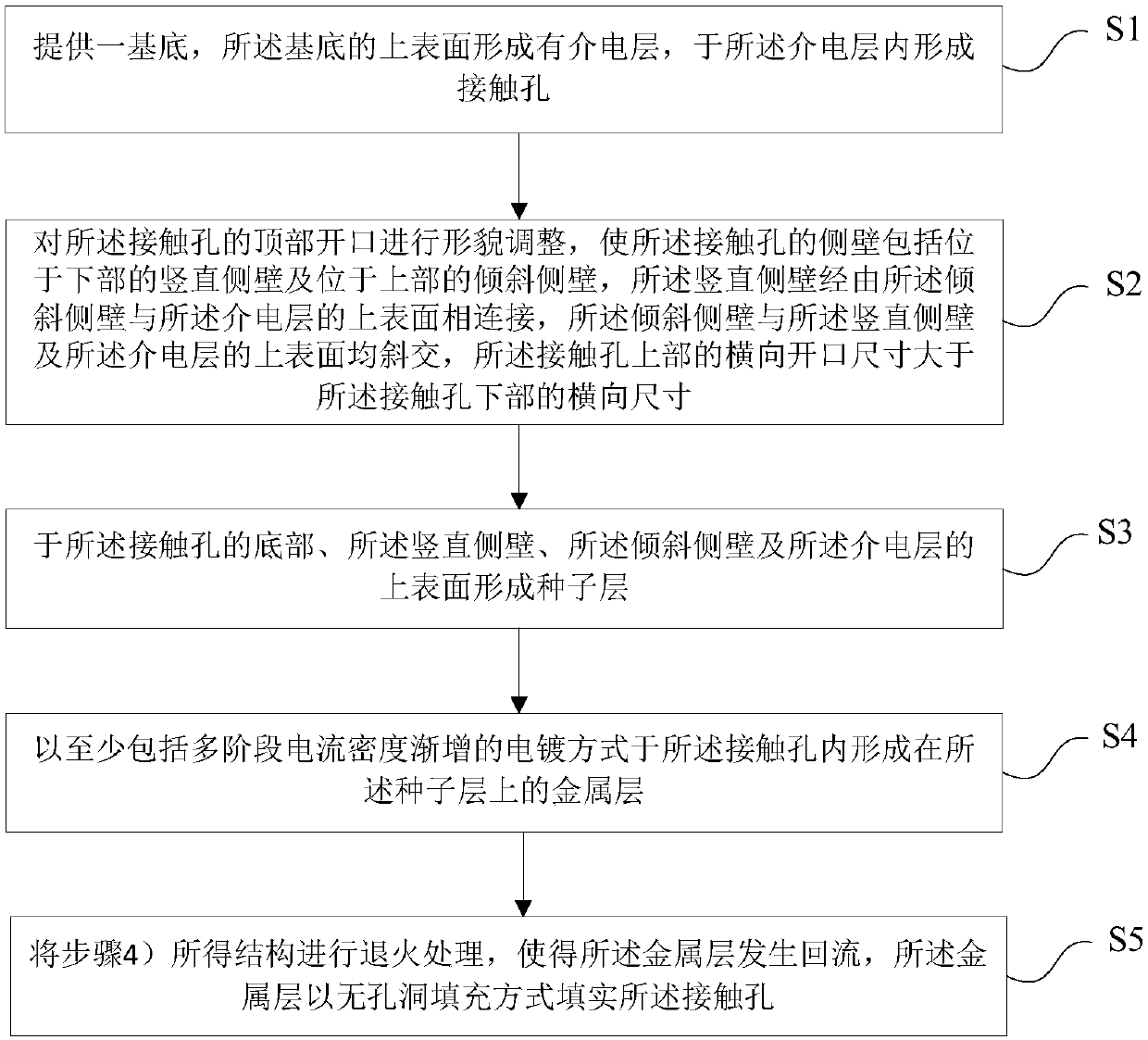
[0077] Such as figure 2 As shown, the present invention provides a method for preparing a semiconductor interconnection structure, and the method for preparing a semiconductor interconnection structure includes the following steps:

[0078] 1) A substrate is provided, a dielectric layer is formed on the upper surface of the substrate, and a contact hole is formed in the dielectric layer;

[0079] 2) Adjusting the shape of the top opening of the contact hole so that the sidewall of the contact hole includes a vertical sidewall at the lower part and an inclined sidewall at the upper part, and the vertical sidewall passes through the inclined sidewall. The wall is connected to the upper surface of the dielectric layer, the inclined side wall is oblique to the vertical side wall and the upper surface of the dielectric layer, and the lateral opening size of the upper part of the contact hole is larger than the The lateral dimension of the lower part of the contact hole;

[0080]...

Embodiment 2

[0122] Please combine Figure 2 to Figure 9 read on Figure 10 to Figure 11 , the present invention also provides a semiconductor interconnection structure, the semiconductor interconnection structure comprising:

[0123] base2;

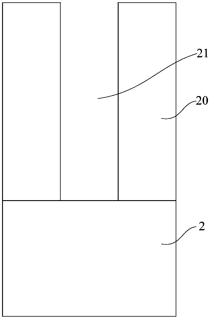
[0124] A dielectric layer 20, the dielectric layer 20 is located on the upper surface of the substrate 2, a contact hole 21 is formed in the dielectric layer 20, and the sidewall of the contact hole 21 includes a vertical sidewall 221 at the bottom And the inclined side wall 222 on the upper part, the vertical side wall 221 is connected with the upper surface of the dielectric layer 20 through the inclined side wall 222, the inclined side wall 222 is connected with the vertical side wall 221 and the upper surface of the dielectric layer 20 are oblique; the lateral opening size of the upper part of the contact hole 21 is larger than the lateral size of the lower part of the contact hole 21;

[0125] a seed layer 26, the seed layer 26 is formed on t...


PUM

PropertyMeasurementUnit
thicknessaaaaaaaaaa
thicknessaaaaaaaaaa
thicknessaaaaaaaaaa

Abstract

The invention provides a semiconductor interconnection structure and a preparation method thereof, and the method comprises the following steps: 1), providing a substrate, forming a dielectric layer on the upper surface of the substrate, and forming a contact hole in the dielectric layer; 2) performing shape adjustment on the top opening of the contact hole to enable the side wall of the contact hole to comprise a vertical side wall and an inclined side wall; 3) forming a seed layer at the bottom of the contact hole, the vertical side wall, the inclined side wall and the upper surface of the dielectric layer; 4) forming a metal layer on the seed layer in the contact hole in an electroplating mode at least including multi-stage current density gradual increase; and 5) annealing the structure obtained in the step 4), so that the metal layer fills the contact hole in a hole-free filling manner. According to the invention, the top morphology of the contact hole is adjusted before the metallayer is filled, so that the generation of overhang can be effectively avoided; and annealing treatment is carried out, so that the metal layer can fill the contact hole in a hole-free manner, the resistance value of the filling metal layer is reduced, and the reliability of the device is improved.

Description

technical field [0001] The invention belongs to the technical field of integrated circuit manufacturing, and in particular relates to a semiconductor interconnection structure and a preparation method thereof. Background technique [0002] Among existing semiconductor processes, tungsten film deposition using chemical vapor deposition (CVD) is a common process in many semiconductor manufacturing. In the existing process, such as figure 1 As shown, generally by placing the dielectric layer 10 on the substrate 10' and having the contact hole 11 formed therein, heating it to the process temperature in a vacuum chamber, first forming the adhesion barrier layer 12 and the contact hole 11 sequentially. After the seed layer 13 , a tungsten metal layer 14 is deposited and formed in the contact hole 11 . [0003] However, as the miniaturization of devices continues to deepen, the size of the semiconductor interconnection structure becomes smaller and smaller. The tungsten metal lay...

Claims


Application Information

Patent Timeline
Patent Type & Authority Applications(China)
IPC IPC(8): H01L21/768H01L23/528
CPCH01L21/76814H01L21/76864H01L21/76873H01L21/76843H01L23/5283
Inventor 不公告发明人
Owner CHANGXIN MEMORY TECH INC
Learn More