
Short-channel silicon carbide MOSFET device integrating Schottky diode and manufacturing method of short-channel silicon carbide MOSFET device

A technology of Schottky diodes and manufacturing methods, which is applied in semiconductor/solid-state device manufacturing, diodes, semiconductor devices, etc., can solve the random discrete distribution of device performance, affect the consistency of device parameters, etc., and reduce the on-resistance Ron , reduce device cost, and improve consistency

Active Publication Date: 2020-04-21
SUZHOU KAIWEITE SEMICON
View PDF8 Cites 0 Cited by
  • Summary
  • Abstract
  • Description
  • Claims
  • Application Information

AI Technical Summary

Problems solved by technology

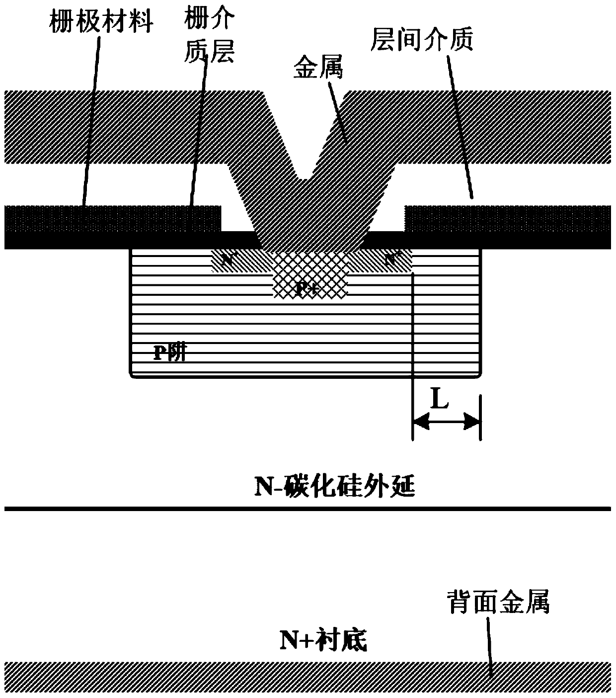
[0003] like figure 1 As shown, the traditional manufacturing method forms the channel length L by photolithography of the P well and the N+ source region. Since the overlay error ΔL inevitably exists between the two layers of lithography, in order to avoid the influence of the overlay error ΔL on the device performance, the When designing the device, it is necessary to take the overlay error ΔL into consideration, and the designed channel length should be L+ΔL, so that the designed silicon carbide MOSFET device has a longer channel length, and the formula Ron=L / [k* W*(VGS-Vth)], it can be seen that due to the increase of L, the on-resistance Ron of MOSFET will inevitably increase; and because the process error is random, it will lead to random discrete distribution of device performance, affecting Device Parameter Consistency

Method used


Image

  • Short-channel silicon carbide MOSFET device integrating Schottky diode and manufacturing method of short-channel silicon carbide MOSFET device
  • Short-channel silicon carbide MOSFET device integrating Schottky diode and manufacturing method of short-channel silicon carbide MOSFET device
  • Short-channel silicon carbide MOSFET device integrating Schottky diode and manufacturing method of short-channel silicon carbide MOSFET device

Examples


Embodiment Construction

[0027] In order to deepen the understanding and recognition of the present invention, the present invention will be further described and introduced below in conjunction with the accompanying drawings.

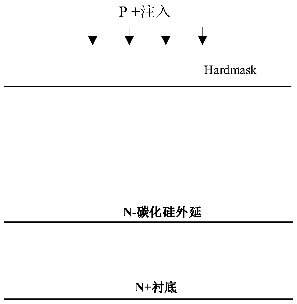
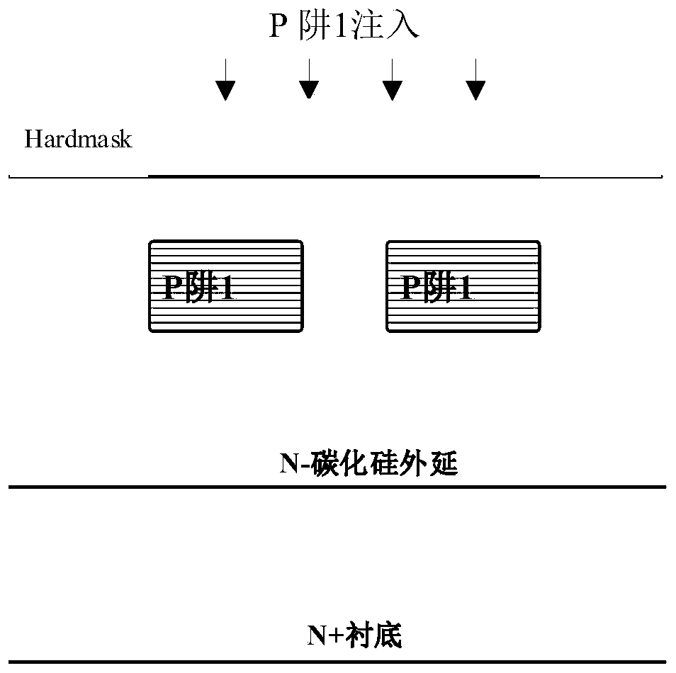
[0028] Such as Figure 2-8 As shown, a method for manufacturing a short-channel silicon carbide MOSFET device integrating a Schottky diode comprises the following steps:

[0029] (1) Deposit an N-silicon carbide epitaxial layer on the upper surface of the N+ silicon carbide substrate. The concentration and thickness of the N-silicon carbide epitaxial layer are determined according to the withstand voltage value of the device. The LPCVD or PECVD process is used on the silicon carbide epitaxial layer Deposit a layer of hardmask, coat photoresist on the hardmask, photolithography and etch the hardmask, and then inject P-type impurities into the silicon carbide epitaxial layer to form a P+ contact, which is used to form the contact of the device well region, using a wet method Or...


PUM


Abstract

The invention relates to a short-channel silicon carbide MOSFET device integrating a Schottky diode and a manufacturing method of the short-channel silicon carbide MOSFET device. The device comprisesa silicon carbide substrate, a silicon carbide epitaxial layer positioned on the silicon carbide substrate, a gate dielectric layer positioned on the silicon carbide epitaxial layer, and an interlayerdielectric layer positioned on the gate dielectric layer; metal is deposited on the back of the silicon carbide substrate to form drain contact; a P-well B region 2 and a P-well A region are arrangedbetween the silicon carbide epitaxial layer and the gate dielectric layer from bottom to top; a P-type impurity ion region and an N-type impurity ion region are arranged in the P-well A region; a gate is arranged on the gate dielectric layer; and a metal layer is deposited on the interlayer dielectric layer to form a source. According to the manufacturing method of the device, P wells B are usedfor manufacturing a side wall, so that an N+ source region is self-aligned with the P wells B, and therefore, a channel length L is realized; the P wells of the source region are separated, an N-epitaxy is enabled to contact with the source end metal; and because the concentration of the N-epitaxy is relatively low, the N-epitaxy and the source end metal form Schottky contact, so that the Schottkydiode is integrated into the short-channel silicon carbide MOSFET.

Description

technical field [0001] The invention relates to the technical field of silicon carbide MOSFET devices, in particular to a short-channel silicon carbide MOSFET device integrated with Schottky diodes through a self-aligned manufacturing method. Background technique [0002] Since the diffusion coefficients of N-type and P-type impurities in silicon carbide are extremely small, it is impossible to achieve channel self-alignment through lateral diffusion of N-well or P-well like silicon-based MOSFETs. At present, silicon carbide MOSFET devices of the traditional method are mainly manufactured by non-self-alignment process. The main process of the process is as follows: ① Deposit an oxide layer on the N-type silicon carbide epitaxy (subsequently called hardmask), P+ photolithography, and etching Oxide layer, glue removal, and then implant P-type impurities to form P+ contact, remove hardmask; ② Deposit oxide layer, P well photolithography, etch oxide layer, remove glue, then inje...

Claims


Application Information

Patent Timeline
IPC IPC(8): H01L21/04H01L29/78
CPCH01L29/7806H01L21/0465H01L29/66068
Inventor 谭在超罗寅丁国华
Owner SUZHOU KAIWEITE SEMICON
Learn More