Coking tail gas treatment method and coking tail gas treatment device

A tail gas treatment and coking tail gas technology, applied in gas treatment, chemical instruments and methods, combined devices, etc., can solve the problems of secondary pollution, tail gas leakage, pollution, etc., and achieve the effect of improving the production and working environment

Active Publication Date: 2020-04-28
CHINA PETROLEUM & CHEM CORP +2
View PDF5 Cites 0 Cited by
  • Summary
  • Abstract
  • Description
  • Claims
  • Application Information

AI Technical Summary

Problems solved by technology

[0006] The purpose of the present invention is to provide a coking tail gas treatment method and device to solve the problem of secondary pollution caused by water vapor, odorous g

Method used


Image

  • Coking tail gas treatment method and coking tail gas treatment device
  • Coking tail gas treatment method and coking tail gas treatment device
  • Coking tail gas treatment method and coking tail gas treatment device

Examples


Embodiment Construction

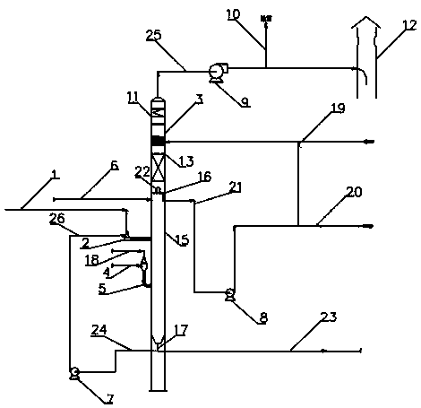
[0053] Such as figure 1 Shown, a coking tail gas desulfurization method comprises the following steps:

[0054] 1) The tail gas of the coke tower and the tail gas generated by other equipment in the coking unit pass through the injection pipeline 6 of the tail gas of the coke tower and the tail gas generated by other equipment in the coking unit, and directly enter the gas-liquid separation section 15 of the tail gas treatment tower 3, and the tail gas of the coke pool is injected into the pipeline through the tail gas of the coke pool 1 enters the tail gas washing facility 2, is washed by circulating washing water, and enters the gas-liquid separation section 15 of the tail gas treatment tower 3 together with the circulating washing water after cooling, and the exhaust steam of the coke tower enters the exhaust steam through the injection pipeline 4 The quenching facility 5 is mixed with the fresh washing water in the discharge steam quenching facility 5, and enters the gas-l...


PUM


Abstract

The invention discloses a coking tail gas treatment method and a coking tail gas treatment device. A purpose of the invention is to solve the problems of secondary pollution and the like caused by vapor and malodorous gas pollution and tail gas VOC and coke powder discharge along with tail gas of the coke pool and the coke powder of the existing delayed coking device. According to the device, cokepool tail gas, coke tower discharge steam, coke tower tail gas and tail gas generated by other equipment in a coking device enter the gas-liquid separation section of a tail gas treatment tower and are subjected to gas-liquid separation; the gas-phase coking tail gas rises to a desulfurization section and is in countercurrent contact with an absorption liquid entering from the upper portion of the desulfurization section so as to be desulfurized; the desulfurized coking tail gas continuously rises to reach a desaturation section; after desaturation, the tail gas is discharged from the top ofthe tail gas treatment tower, VOC is removed, and then the tail gas is emptied; the rich absorption liquid is pumped out, pressurized and returned to the upper portion of the desulfurization section;after failure, the waste liquid is externally sent to a treatment unit; and the washing water containing solid particles in the tail gas treatment tower enters a settling section downwards, the washing sewage containing solid particles comes out from the bottom of the tail gas treatment tower, and the clarified washing water comes out from a washing water pumping hopper at the lower portion of thetail gas treatment tower and is pressurized so as to be recycled as circulating washing water.comes out from the top of the tail gas treatment tower, VOC is removed, and then the tail gas is emptied;the rich absorption liquid is pumped out, pressurized and returned to the upper portion of the desulfurization section; after failure, the waste liquid is sent to a treatment unit; and the washing water in the tail gas treatment tower flows out downwards from the bottom of the tail gas treatment tower, one part is discharged out of the device, and the other part is pressurized and then recycled as circulating washing water.

Description

technical field [0001] The invention belongs to the field of coking tail gas treatment in petroleum processing, and relates to a coking tail gas treatment method and device. Background technique [0002] Delayed coking process is an important residual oil processing process in petroleum processing. After the raw material is heated to about 500°C by heat exchange and coking furnace, it enters the coke tower for thermal cracking reaction and condensation reaction, and generates oil gas and solid coke in the coke tower. The oil and gas generated by the pyrolysis reaction enters the fractionation tower through the oil and gas line at the top of the coke tower, and is separated into rich gas and fractions such as naphtha, diesel oil, and wax oil. Solid coke is deposited in the coke tower and is regularly decoked to the coke pool. [0003] In the coking process, high-pressure water is usually used for drilling and coke cutting, and the cut and crushed coke blocks enter the coke ...

Claims


Application Information

Patent Timeline
IPC IPC(8): B01D53/78B01D53/72B01D53/48B01D53/00B01D50/00
CPCB01D53/78B01D53/48B01D53/002B01D53/72B01D2257/708B01D50/40Y02A50/20
Inventor 朱华兴李和杰杜翔沈晓艳刘艳曹克腾
Owner CHINA PETROLEUM & CHEM CORP
Why Eureka
Try Eureka