
Welded joint fatigue life prolonging method

A welded joint and fatigue technology, which is applied in the field of fatigue life extension of welded joints, can solve the problems of reducing stress level, reducing fatigue life, and local stress concentration on the surface of components, so as to improve fatigue performance and wear resistance, increase surface strength and hardness, Effect of improving fatigue life

Active Publication Date: 2020-04-28
INST OF METAL RESEARCH - CHINESE ACAD OF SCI
View PDF7 Cites 2 Cited by
  • Summary
  • Abstract
  • Description
  • Claims
  • Application Information

AI Technical Summary

Problems solved by technology

However, shot peening is a surface strengthening method that mainly introduces residual compressive stress to the surface of metal components. The existence of residual compressive stress reduces the stress level and ultimately improves the fatigue life of components. However, residual stress is easy to release, the energy conversion rate is low, and the effect of fatigue life extension is significantly lower than that of the strengthening method with grain refinement as the main strengthening mechanism
Disadvantages of shot peening: 1) Due to the irregular bombardment of a large number of shot particles on the metal surface, the roughness of the processed surface becomes larger, and even micro-cracks are generated, which makes the local stress concentration on the surface of the component and reduces the fatigue life
2) For some metal welded components with irregular shapes such as fillet welds, shot peening is a very effective surface strengthening method, but for some butt welded metal components with regular shapes, the shot peening ability is slightly insufficient
3) The surface roughness of shot peening components is difficult to control

Method used


Image

  • Welded joint fatigue life prolonging method
  • Welded joint fatigue life prolonging method
  • Welded joint fatigue life prolonging method

Examples


Embodiment 1

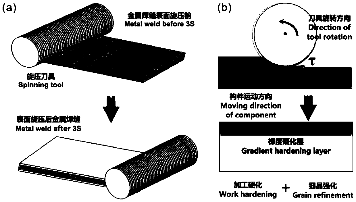
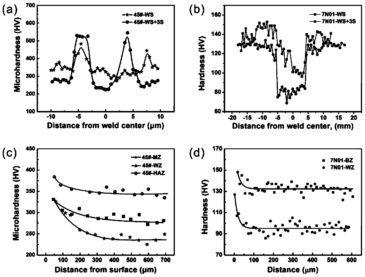
[0056] This embodiment is the surface spinning strengthening process of 45# steel welded joints. For the 45# steel (tensile strength 500MPa-1000MPa) of this embodiment, in order to ensure the input of the required compressive stress and shear stress for surface strengthening, it can simultaneously achieve For better surface finish, choose a tool with a double helix machining blade with a pitch value of 200mm, a tooth thickness of 1.5mm, a tooth width of 2mm, and a helical groove depth of 1.5mm.

[0057] The surface spinning process of the present embodiment is as follows:

[0058] Step 1: Work piece welding. Two 45# steel base metal plates were butt welded with ER-70S-6 low carbon steel welding wire, and the welding method was non-melting inert gas shielded welding (TIG).

[0059] Step 2: Spinning tool and workpiece clamping. Install the spinning tool on the bearing of the spinning machine, and clamp the workpiece on the worktable. The processed surface of the workpiece is p...

Embodiment 2

[0068] This embodiment is the surface spinning strengthening process of 7N01 aluminum alloy welded joints. For the aluminum alloy with high plasticity in this embodiment, in order to obtain a lower surface roughness, the pitch value of the double helix processing blade is 400mm. A tool with a tooth thickness of 0.3mm, a tooth width of 1.5mm, and a helical groove depth of 0.3mm.

[0069] The surface spinning process of the present embodiment is as follows:

[0070] Step 1: Work piece welding. Two 7N01 aluminum alloy base metal plates were butt welded with 5356 aluminum alloy welding wire, and the welding method was molten inert gas shielded welding (MIG).

[0071] Step 2: Spinning tool and workpiece clamping. Install the spinning tool on the bearing of the spinning machine, and clamp the workpiece on the worktable. The processed surface of the workpiece is parallel to the axis of the spinning tool.

[0072] Step 3: Calibrate the knife. The worktable and the spinning tool ar...


PUM

PropertyMeasurementUnit
thicknessaaaaaaaaaa
thicknessaaaaaaaaaa
tensile strengthaaaaaaaaaa

Abstract

The invention discloses a welded joint fatigue life prolonging method and belongs to the technical field of surface strengthening processing for improving the fatigue property of a metal welding seam.According to the welded joint fatigue life prolonging method, the surface spinning strengthening technology is adopted to carry out surface strengthening processing on a welded joint so as to obtaina metal surface layer microstructure with hardness gradient, so that surface strengthening and hardening of the metal welded joint are realized; and in addition, the processing surface is smooth, so that the surface stress concentration level and the postwelding residual stress level of a welded component are lowered. When the metal welded component takes service under the action of cyclic load, afatigue crack can be restrained from generating on the surface of the welded joint after spinning processing to improve the fatigue property of the metal welded joint.

Description

technical field [0001] The invention relates to the technical field of surface strengthening processing for improving the fatigue performance of metal welds, in particular to a fatigue life extension method for welded joints. Background technique [0002] With the continuous development of lightweight high-speed trains, improving the safety and reliability of key train components has become an indispensable key scientific issue. For a large number of key components of high-speed trains, welding is an important forming technology. Therefore, improving the reliability of these welded components has become an important link to ensure the safety and reliability of trains. According to statistics, high-speed trains have as many as 38 kinds of welds, the thinnest is 2mm, and the thickest is 17mm. Due to the large local input of energy during the welding forming process, the microstructure of the weld area changes. Due to the non-uniformity of the structure and mechanical properti...

Claims


Application Information

Patent Timeline
Patent Type & Authority Applications(China)
IPC IPC(8): B23D79/00
CPCB23D79/00
Inventor 王强王董琪琼张哲峰
Owner INST OF METAL RESEARCH - CHINESE ACAD OF SCI
Learn More