Method for laser welding of clad metal workpiece through CO2 laser device

A technology for laser welding and metal workpieces, applied in laser welding equipment, metal processing equipment, welding media, etc., can solve the problems of high welding cost, low quality, and hindering laser absorption, so as to improve welding quality, reduce manufacturing costs, and improve The effect of absorption rate

Pending Publication Date: 2020-05-08
上海中科神光光电产业有限公司
View PDF5 Cites 0 Cited by
  • Summary
  • Abstract
  • Description
  • Claims
  • Application Information

AI Technical Summary

Problems solved by technology

But in actual welding, using CO 2 When laser welding metal workpieces, due to the long wavelength of this type of laser, the metal workpiece itself has a low absorption rate of laser light, and the coating on the surface of the metal workpiece with a low melting point coating will evaporate during the welding process to generate more plasma. to CO 2 The high laser absorption rate will seriously hinder the absorption of laser by the metal workpiece, resulting in small weld penetration, low quality, and low strength. Therefore, more power is usually required during welding, resulting in increased energy consumption and cost.
In addition, in actual welding, since air has a harmful effect on the weld metal, it is necessary to add shielding gas from the outside to discharge the air during welding. The most widely used shielding gas is He, Ar and other inert gases, but the price of inert gases is very expensive. , which also results in higher soldering costs

Method used


Image

  • Method for laser welding of clad metal workpiece through CO2 laser device
  • Method for laser welding of clad metal workpiece through CO2 laser device
  • Method for laser welding of clad metal workpiece through CO2 laser device

Examples


Embodiment 1

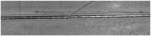
[0037] Such as figure 2 , Figure 5 Shown is the weld surface and cross-sectional topography of an embodiment obtained by using the welding method of the present invention. Among them, the welding workpieces are low-alloy high-strength steel plates with a thickness of 0.9mm and 1.4mm, and the surface is a hot-dip galvanized layer. This material is widely used in the manufacture of automobile bodies, and the welding assembly form is butt welding; laser welding power It is 2Kw, the welding speed is 2.3m / min, and the shielding gas is 98% Ar+2% O 2 , the gas flow rate is 15L / min.

[0038] Depend on figure 2 It can be seen that adding 2% O 2 After being used as a shielding gas, the surface quality of the weld is good, and no obvious oxidation phenomenon is observed in the weld. Depend on Figure 5 It can be seen that the cross-section of the weld nugget is well formed, and the diameter of the bottom nugget is 0.76mm.

Embodiment 2

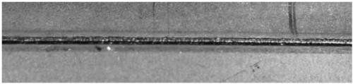
[0040] Such as image 3 , Figure 6 Shown is the weld surface and cross-sectional topography of another embodiment obtained by using the welding method of the present invention. Among them, the welding materials are low-alloy high-strength steel plates with a thickness of 0.9mm and 1.4mm, and the surface is hot-dip galvanized. The welding assembly form is butt welding; the laser welding power is 2Kw, the welding speed is 2.3m / min, and the shielding gas is 95% Ar+5% O 2 , the gas flow rate is 15L / min.

[0041] Depend on image 3 It can be seen that adding 5% O 2 After being used as a shielding gas, the surface quality of the weld is good, and no obvious oxidation phenomenon is observed in the weld. Depend on Figure 6 It can be seen that the cross-section of the weld is well formed, and the diameter of the bottom nugget is 0.81mm.


PUM

PropertyMeasurementUnit
Thicknessaaaaaaaaaa
Thicknessaaaaaaaaaa

Abstract

The invention discloses a method for laser welding of a clad metal workpiece through a CO2 laser device. By adding a certain ratio of O2 to traditional protective gas during welding and making O2 react with a low-melting-point clad layer to generate oxides, the absorption rate of the metal workpiece for lasers is increased, the depth of fusion of welded joints is increased, and therefore the welding quality is improved; and in addition, the use ratio of inert gas is reduced, so that welding cost is reduced, and the aims of obtaining higher-quality weld joints and reducing cost are realized onthe whole.

Description

technical field [0001] The invention relates to a laser welding method for a metal workpiece with a low-melting point coating, in particular to a laser welding method for a galvanized steel plate in industries such as automobile industry, aviation, shipbuilding, railway and building construction. Background technique [0002] In order to make the metal workpiece have good anti-corrosion effect, the surface of the workpiece is usually coated with a layer of anti-corrosion low melting point coating, especially zinc coating. Galvanized steel sheet is widely used for its low cost and excellent corrosion resistance, especially in automobiles, aviation , shipbuilding, railway and housing construction and other fields. Laser welding is an efficient and precise welding method that uses a high-energy-density laser beam as a heat source, and is increasingly used in the welding of metal workpieces. But in actual welding, using CO 2 When laser welding metal workpieces, due to the long...

Claims


Application Information

Patent Timeline
IPC IPC(8): B23K26/21B23K26/14B23K26/322B23K35/38
CPCB23K26/14B23K26/322B23K35/38B23K26/21
Inventor 杨上陆王艳俊姚斌
Owner 上海中科神光光电产业有限公司
Why Eureka
Try Eureka