Efficient waste heat recovery and denitration combined technology for gas turbine tail gas

A gas turbine and waste heat recovery technology, which is applied in the fields of flue gas denitrification and waste heat recovery, can solve the problems of insufficient waste heat recovery, increased shutdown risk, and high operating costs, and achieve the effects of improving comprehensive utilization, reducing shutdown risks, and low operating costs

Inactive Publication Date: 2020-05-19
ZHEJIANG SATELLITE ENERGY CO LTD
View PDF6 Cites 1 Cited by
  • Summary
  • Abstract
  • Description
  • Claims
  • Application Information

AI Technical Summary

Problems solved by technology

However, the device has disadvantages such as high energy consumption, high investment cost, high maintenance pressure, high operating cost, and low stability, so it is not suitable for continuous chemical production that focuses on stability.
[0007] Chinese Patent Application No. 201620886151.6 discloses a bypass flue gas denitrification system for gas turbine exhaust. This patented technology uses the flue gas denitrification system to denitrify the flue gas, and uses the waste heat boiler to recover waste heat, basically realizing the technical transformation of the power plant, but the Technology application has disadvantages such as high failure rate in the continuous application of chemical automation, which increases the risk of shutdown, and the waste heat is not fully recovered.

Method used


Image

  • Efficient waste heat recovery and denitration combined technology for gas turbine tail gas
  • Efficient waste heat recovery and denitration combined technology for gas turbine tail gas

Examples


Embodiment Construction

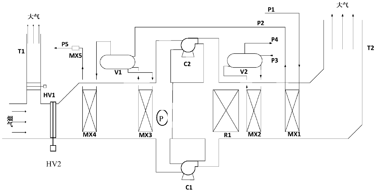
[0027] see figure 1 , the process for high-efficiency waste heat recovery and denitrification of gas turbine tail gas described in the present invention,

[0028] The 520°C flue gas discharged from the gas turbine enters the flue gas denitrification system through the HV2 control valve, exchanges heat with the saturated steam from the high-pressure drum V1 through the superheating section MX4 of the high-pressure boiler, cools to 420°C, and then passes through the evaporating section MX3 of the high-pressure boiler and The high-pressure boiler water from the high-pressure steam drum V1 is heat-exchanged, cooled to 220°C, and then enters the denitration reaction bed R1 through the fan C1 (fan C2 is standby) to contact the SCR denitration catalyst for denitration reaction, so that the nitrogen oxides in the flue gas content reduced to 30mg / Nm 3 , and then the flue gas passes through the low-pressure boiler evaporation section MX2 to exchange heat with the low-pressure boiler wa...


PUM


Abstract

The invention provides an efficient waste heat recovery and denitration combined technology for gas turbine tail gas. Flue gas discharged from a gas turbine enters a flue gas denitration system, is subjected to heat exchange with saturated steam from a high-pressure steam drum through a superheating segment of a high-pressure boiler, then is subjected to heat exchange with high-pressure boiler water from the high-pressure steam drum through an evaporation segment of the high-pressure boiler, then enters a denitration reaction bed layer through a fan to make contact with a catalyst for a denitration reaction, then is subjected to heat exchange with low-pressure boiler water from a low-pressure steam drum through an evaporation segment of a low-pressure boiler, and finally is subjected to heat exchange with the high-pressure boiler water at a coal-saving segment of the high-pressure boiler and then is discharged through a chimney. According to the efficient waste heat recovery and denitration combined technology, the high-pressure steam drum and the low-pressure steam drum are subjected to heat exchange with the flue gas to generate high-pressure steam and low-pressure steam, waste heat in the flue gas is recovered maximally, thus the comprehensive utilization rate of the gas turbine is increased and reaches 95% or above, the operation and investment costs are lowered, and the energy saving and environment friendly requirements are met.

Description

technical field [0001] The invention belongs to the technical field of flue gas denitrification and waste heat recovery, and in particular relates to a process for gas turbine high-efficiency waste heat recovery and denitrification combined use. Background technique [0002] As the country's requirements for environmental protection and chemical energy consumption are getting higher and higher, gas turbines are more and more widely used in chemical automation, and the energy saving effect is more obvious than traditional steam turbines and motors as driving forces. As the country's air pollution control requirements are becoming increasingly strict, the types of pollutants that are restricted to be discharged are also gradually increasing. The emission control requirements for nitrogen oxides and dust have been clarified and enforced many times. Mandatory implementation of emissions to be 50mg / Nm 3 the following. Therefore, in order to meet the requirements of environmenta...

Claims


Application Information

Patent Timeline
Patent Type & Authority Applications(China)
IPC IPC(8): F22B1/18B01D53/56B01D53/94
CPCB01D53/56B01D53/9409F22B1/1815
Inventor 杨卫东高军田俊凯汪红亮陆朝阳范昌海寇亮周轶
Owner ZHEJIANG SATELLITE ENERGY CO LTD
Why Eureka
Try Eureka