
Ka-band solid-state power amplifier predistorter

A solid-state power and predistorter technology, applied in power amplifiers, improved amplifiers to reduce nonlinear distortion, amplifiers, etc., can solve the problem of predistortion amplitude and phase controllability and adjustability that are difficult to meet strong nonlinear predistortion requirements and other problems, to achieve the effect of meeting the linearization requirements of nonlinear predistortion, high compensation accuracy, and convenient design

Inactive Publication Date: 2020-06-05
SOUTHWEAT UNIV OF SCI & TECH
View PDF7 Cites 3 Cited by
  • Summary
  • Abstract
  • Description
  • Claims
  • Application Information

AI Technical Summary

Problems solved by technology

[0007] The purpose of the present invention is to provide a Ka-band solid-state power amplifier predistorter, which solves the problem that the existing reflective nonlinear predistortion signal generation method is difficult to meet the strong nonlinear predistortion requirements and the controllability and controllability of the predistortion amplitude and phase. tonality problem

Method used


Image

  • Ka-band solid-state power amplifier predistorter
  • Ka-band solid-state power amplifier predistorter
  • Ka-band solid-state power amplifier predistorter

Examples


Embodiment 1

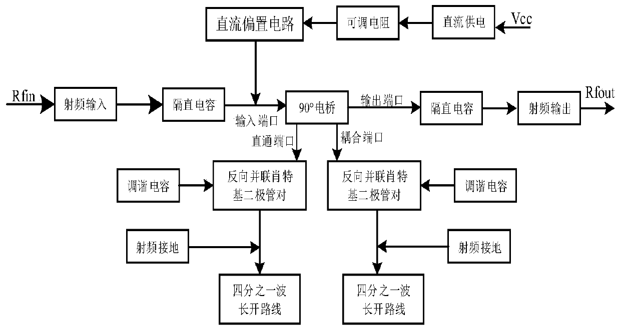
[0027] like figure 1 As shown, the Ka-band solid-state power amplifier predistorter provided by the preferred embodiment of the present invention includes a 90° electric bridge, two sets of anti-parallel Schottky diode pairs, a DC bias circuit, two tuning capacitors and two isolation A straight capacitor, the output port of the 90° electric bridge is connected to the output port of the radio frequency signal through one of the DC blocking capacitors; the coupling port of the 90° electric bridge is connected to one end of a set of antiparallel Schottky diode pairs , the other end of the anti-parallel Schottky diode pair is connected to a quarter open-circuit wavelength line of the center frequency of the designed frequency band; One end of the diode pair is connected, and the other end of the anti-parallel Schottky diode pair is connected with a quarter open-circuit wavelength line of the center frequency of the design frequency band; the DC blocking capacitor of the input port...

Embodiment 2

[0031] On the basis of Example 1, a specific implementation is provided. The DC bias circuit includes a voltage dividing current limiting resistor, a bias high resistance line and a sector capacitor, and the DC power supply enters the bias through the voltage dividing current limiting resistor. A high-impedance line and a fan-shaped capacitor, the bias high-resistance line provides DC power to the Schottky diode, and the fan-shaped capacitor is grounded.

[0032] Preferably, the lengths of the bias high-impedance line and the two sectors of the sector capacitor are both a quarter wavelength of the center frequency of the designed frequency band.

[0033] Wherein, the anti-parallel Schottky diode pair realizes radio frequency grounding through a high resistance line and a fan-shaped microstrip line.

[0034] Preferably, the lengths of the high resistance line and the fan-shaped microstrip line are both a quarter wavelength of the center frequency of the designed frequency band....


PUM

PropertyMeasurementUnit
impedanceaaaaaaaaaa

Abstract

The invention discloses a Ka-band solid-state power amplifier predistorter. An output port of a 90-degree bridge is connected with an output port of a radio frequency signal through a blocking capacitor; a coupling port of the 90-degree bridge is connected with one end of one anti-parallel Schottky diode pair, and the other end of the anti-parallel Schottky diode pair is connected with a quarter open-circuit wavelength line of the center frequency of a designed frequency band; a straight-through port of the 90-degree bridge is connected with one end of the other anti-parallel Schottky diode pair, and the other end of the anti-parallel Schottky diode pair is connected with a quarter open-circuit wavelength line of the center frequency of the designed frequency band; a blocking capacitor atan input port of the 90-degree bridge is connected in parallel with a direct-current bias circuit; and the ends, connected with the corresponding quarter open-circuit wavelength lines, of the two anti-parallel Schottky diode pairs are grounded in a radio frequency mode, and the two anti-parallel Schottky diode pairs are each connected with a corresponding tuning capacitor. The structure is simple,and the application capability of the pre-distortion circuit is improved; and the compensation precision is high, and the nonlinear pre-distortion linearization requirement of a power amplifier can be met.

Description

technical field [0001] The invention belongs to the technical field of communication equipment, and relates to a Ka-band solid-state power amplifier predistorter. Background technique [0002] With the continuous development of electronic communication technology, on the one hand, the lower-end electromagnetic spectrum has been fully excavated and used by people, and the spectrum resources in the civil communication field are becoming more and more scarce. The military communication field has special requirements for high-frequency spectrum with better confidentiality. Use requirements; on the other hand, large data capacity and high data transmission rate are the development trends of modern wireless communication systems, so the development and utilization of microwave and millimeter wave frequency bands with wider operating frequency bands and higher information capacity has become increasingly urgent. Usually, electromagnetic waves with a frequency domain of 30-300GHz (w...

Claims


Application Information

Patent Timeline
Patent Type & Authority Applications(China)
IPC IPC(8): H03F3/21H03F1/32
CPCH03F3/21H03F1/3247
Inventor 姚权
Owner SOUTHWEAT UNIV OF SCI & TECH
Learn More