Stud embedding device on roller of mine high-pressure roller mill and repair welding process thereof

A high-pressure roller mill and stud technology, applied in the field of machinery, can solve the problems of wear and tear, affecting the effect of ore abrasives, etc., and achieve the effects of high work efficiency, reduced labor intensity, and reduced maintenance costs.

Pending Publication Date: 2020-06-19
ANHUI MA STEEL EQUIP MAINTENANCE CO LTD
View PDF0 Cites 0 Cited by
  • Summary
  • Abstract
  • Description
  • Claims
  • Application Information

AI Technical Summary

Problems solved by technology

Although the studs on the squeeze roller are made of high wear-resistant and high-toughness materials, the studs on the roller surface will be worn and broken after long-term use, especially near the shoulders on both sides of the roller. Replanting studs and welding repairs on both sides of the wear will inevitably affect the abrasive effect of the ore

Method used


Image

  • Stud embedding device on roller of mine high-pressure roller mill and repair welding process thereof
  • Stud embedding device on roller of mine high-pressure roller mill and repair welding process thereof
  • Stud embedding device on roller of mine high-pressure roller mill and repair welding process thereof

Examples


Embodiment 1

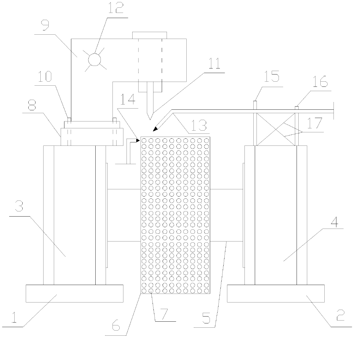
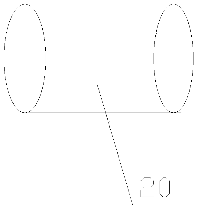
[0036] Such as figure 1 with figure 2 As shown, the present invention is a stud inlay device on the roller of a mine high-pressure roller mill. The high-pressure roller mill includes a left frame 3 and a right frame 4, and the left frame 3 and the right frame 4 is provided with a squeeze roller 6 through a universal coupling 5, and a number of studs 20 are uniformly arranged on the outside of the squeeze roller 6. It is characterized in that the bottom of the left frame 3 and the right frame 4 The left side sleeper 1 and the right side sleeper 2 are respectively provided with; the top of the left side frame 3 is provided with a stud inlay drilling device, and the right side frame 4 is provided with a heating device; the stud inlay device A welding torch 14 is also included. In the present embodiment, two left and right side sleepers 1, 2 are set under the left and right side frames 3, 4, which can ensure enough height to make the squeeze roller 6 operate and play the role o...

Embodiment 2

[0042] The welding repair process of the stud inlay device on the roller of a mine high pressure roller mill described in Example 1 is characterized in that it comprises the following steps:

[0043] Step 1. Preparation before welding;

[0044] 1.1), gas welding equipment: H01-12 welding torch, 3# welding nozzle, hose hoop, oxygen acetylene bottle, oxygen acetylene wind belt;

[0045] 1.2) Heating device: H01-20 roasting gun, 3# welding nozzle, throat hoop, oxygen-acetylene bottle, oxygen-acetylene wind belt;

[0046] 1.3), Auxiliary facilities: angle grinder, file, hand hammer, flat shovel, colored glasses, copper needle, sheepskin gloves, sample, thermometer and magnifying glass, etc.;

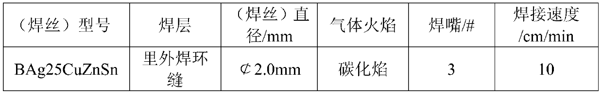
[0047] 1.4), Welding position: Rotary welding at the horizontal ring peak welding position;

[0048] 1.5) Welding requirements: All welding deposits must have no welding defects and be metallurgically fused to the base metal;

[0049] 1.6), welding material: BAg25CuZnSn, with good fluidity ...


PUM

PropertyMeasurementUnit
thicknessaaaaaaaaaa
diameteraaaaaaaaaa

Abstract

The invention discloses a stud embedding device on a roller of a mine high-pressure roller mill and a repair welding process thereof. The high-pressure roller mill comprises a left side rack and a right side rack, wherein an extrusion roller is arranged on the left side rack and the right side rack through an universal coupling, a plurality of studs are evenly arranged on the outer side of the extrusion roller, a left side sleeper and a right side sleeper are arranged at the bottoms of the left side rack and the right side rack respectively, a stud embedding and drilling device is arranged atthe top of the left rack, a heating device is arranged on the right rack, and the stud embedding device further comprises a welding gun. The stud embedding device and the repair welding process thereof have the advantages of being safe, easy to operate, stable in welding quality, low in investment cost, high in working efficiency and capable of meeting actual field requirements, greatly reducing maintenance cost, reducing shutdown loss, reducing labor intensity of workers and providing guarantee for reasonable production assembly, and meanwhile, the stud embedding device on the roller of the mine high-pressure roller mill and the repair welding process provide scientific reference basis for online repair of other mine large workpieces.

Description

technical field [0001] The invention belongs to the field of machinery, and in particular relates to a stud inlay device on a roller of a mine high-pressure roller mill and a welding repair process thereof. Background technique [0002] With the development of mineral processing technology and equipment at home and abroad, high-pressure roller mills are used more and more widely as mineral processing equipment. High-pressure ball mills are mainly composed of frame, extrusion rollers, reducers, universal couplings and motors. The rollers are placed in pairs on the frame in parallel, and the loose material is squeezed between the two rollers, and the volume decreases in a short time, and finally reaches the highest value at the smallest gap between the two rollers, and the solid material particles are broken in an instant. At present, the roller adopts the roller sleeve structure with studs on the outside of the roller shaft. The studs are embedded in the base body of the roll...

Claims


Application Information

Patent Timeline
Patent Type & Authority Applications(China)
IPC IPC(8): B23P6/00B23K5/18B23K5/00
CPCB23K5/006B23K5/18B23P6/00
Inventor 范兴海许杰峰章锐涂俊魁王东正蒲晓庆
Owner ANHUI MA STEEL EQUIP MAINTENANCE CO LTD
Why Eureka
Try Eureka