Numerical control machine tool cutter state monitoring and control system and method

A technology of CNC machine tools and control methods, which is applied in general control systems, control/regulation systems, computer control and other directions, can solve the problems of misjudgment of tool status, reduced stability, low adaptability and accuracy, etc. High accuracy and guaranteed accuracy

Active Publication Date: 2020-06-30
QINGDAO TECHNOLOGICAL UNIVERSITY +1
View PDF8 Cites 22 Cited by
  • Summary
  • Abstract
  • Description
  • Claims
  • Application Information

AI Technical Summary

Problems solved by technology

However, due to the ever-changing manufacturing process, the selected tools are also different, so the monitoring system of the equipment itself has low adaptability and accuracy to tool monitoring.
[0006] The inventor found in the research that the existing tool detection system uses the detection of cutting force as the basis for state judgment, which makes the overall resolution of the system low, and the factors that cause the change of cutting force during the machining process are very complicated, so the system is easy to detect the cutting force. The state makes a misjudgment, which affects the normal processing of the machine tool
[0007] There are also tool detection systems that need to add different types of sensors to the system. The developed system needs to fuse multiple sensors, which reduces the stability of the system's working process.
At the same time, since the installation of the sensor needs to be close to the tool and its nearby connectors, the sensor and the system processor need to be connected for data transmission, which largely interferes with the normal processing of the machine tool and hinders the application of this tool state monitoring method in actual production.
[0008] There are also tool detection methods that can effectively monitor the status of abnormal tools. However, as enterprises continue to move forward from traditional manufacturing to intelligent manufacturing, the accuracy requirements for tool status monitoring are getting higher and higher, and real-time performance must also meet production requirements. Therefore, the effective monitoring of the abnormal state of the tool alone no longer meets the technical requirements for the transformation of the enterprise's automated production line to the intelligent production line. Therefore, the online state monitoring of the tool has higher precision and better real-time technical requirements.
[0009] In addition, in the actual machining process, the speed of tool rotation varies widely, and there are factors such as cutting lubrication methods in the machining process that change, so that the existing device cannot monitor the tool state very well under certain working conditions. Function
[0010] The detection rhythm of the machine tool tool in-position detection system of the machine vision in the prior art cannot be autonomous, or the setting of the detection time node is performed manually, or the automatic detection rhythm is set according to past experience. In this aspect of automatic detection Relatively lack of intelligence

Method used


Image

  • Numerical control machine tool cutter state monitoring and control system and method
  • Numerical control machine tool cutter state monitoring and control system and method
  • Numerical control machine tool cutter state monitoring and control system and method

Examples


Embodiment 1

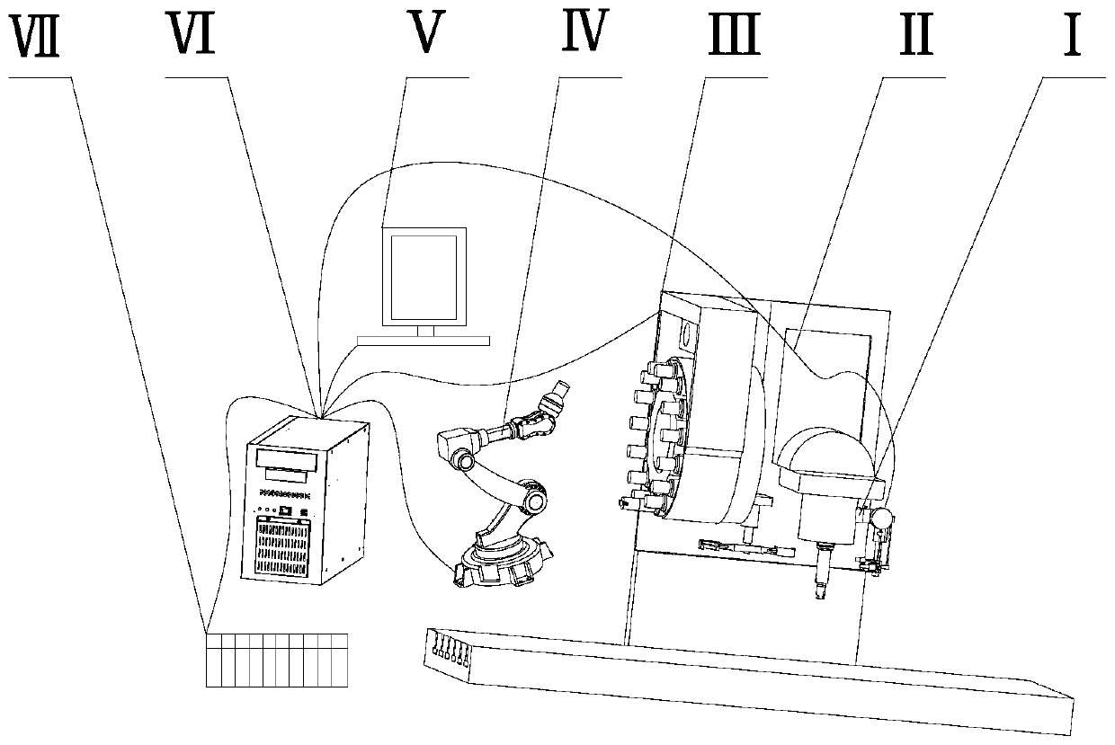
[0118] See attached figure 1 As shown, this embodiment discloses a CNC machine tool tool state monitoring and control system, including data acquisition unit Ⅰ, data analysis and processing unit Ⅱ, database unit Ⅶ, decision-making and control unit Ⅵ, intelligent tool magazine unit Ⅲ, display unit Ⅴ and abnormal Tool delivery unit Ⅳ. The system can realize accurate judgment of tool status through data acquisition and data analysis and processing unit. The intelligent tool magazine unit and decision-making and control unit realize the replacement of new tools when the machine tool is abnormal, the accurate judgment and classification of abnormal tools, and subsequent intelligent processing.

[0119] In an implementation example, Figure 23 It is a schematic diagram of the connection of each unit of the system; the data acquisition unit includes a power sensor, a data acquisition card, an industrial CCD camera and an AD converter, completes the data acquisition and transmits it ...

Embodiment 2

[0178] This implementation example discloses a CNC machine tool tool state monitoring and control method, Figure 24 It is the working flow chart of the machine tool after the initial judgment of tool abnormality; Figure 25 It is a schematic diagram of the wear of the replaceable tool blade; Figure 27 It is the schematic diagram of the tool initial judgment module; including:

[0179] The data acquisition unit and the data analysis and processing unit are divided into two subsystems, which are used for pre-judgment and accurate judgment of the tool state respectively.

[0180] The way to realize the pre-judgment of the tool state is as follows:

[0181] Through the vibration sensor inside the intelligent tool holder, the vibration signal during the machining process is detected and used as the signal input for the system tool detection pre-judgment.

[0182] The vibration sensor is integrated inside the intelligent tool handle and uses wireless transmission inside the too...


PUM


Abstract

The invention discloses a numerical control machine tool cutter state monitoring and control system and control method. The control method is characterized in that abnormal vibration signals in the cutter machining process are collected in real time; state pre-judgment is carried out on an abnormal condition by using a cutter state pre-judgment model, and a time point when a cutter is abnormal isdetermined; and after the state is pre-judged and under the condition of not influencing the cutter machining continuity, cutter image acquisition is completed, so that accurate judgment on the abnormal state of the cutter is realized. The system is divided into state pre-judgment and accurate judgment of the cutter in terms of cutter state judgment, and the system occupies short equipment normaloperation time in the working process, so that the working efficiency of a machine tool is effectively improved; and the cutter state pre-judgment in the system is based on the machine learning theoryprinciple, and the accurate judgment of the cutter state is based on the image comparison and analysis processing method.

Description

technical field [0001] The invention belongs to the field of state monitoring of numerical control equipment, and in particular relates to a state monitoring and control system and method of a numerical control machine tool tool. Background technique [0002] The statements in this section merely provide background information related to the present disclosure and do not necessarily constitute prior art. [0003] As the basic equipment of the manufacturing and processing industry, machine tools are of great significance to monitor their condition. In the CNC machining process, the guarantee of product quality and the safety of the machining process are inseparable from the real-time monitoring of the tools of the CNC equipment. The status monitoring is an important part of the monitoring of the CNC equipment. Real-time monitoring and effective control measures will have varying degrees of impact on the continuity of the processing process and cause immeasurable losses to th...

Claims


Application Information

Patent Timeline
Patent Type & Authority Applications(China)
IPC IPC(8): B23Q17/09G05B19/4065
CPCB23Q17/09G05B19/4065Y02P90/02
Inventor 李长河尹硕罗亮吉卫喜万斌辉李昊罡曹华军卢秉恒唐立志张彦彬徐杰罗慧明徐海州杨敏洪华平高腾侯亚丽马五星陈帅
Owner QINGDAO TECHNOLOGICAL UNIVERSITY
Why Eureka
Try Eureka