Waste gas treatment device used in kitchen waste biochemical treatment equipment

A waste gas treatment device and biochemical treatment technology, which is applied in the direction of combined devices, gas treatment, and the use of liquid separation agents, can solve the problems of affecting the surrounding environment, unfavorable life of surrounding residents, and high energy loss, and achieve the effect of eliminating visual pollution

Pending Publication Date: 2020-07-14
BEIJING CPCEP ENERGY CONSERVATION & ENVIRONMENTAL PROTECTION TECH CO LTD
View PDF0 Cites 3 Cited by
  • Summary
  • Abstract
  • Description
  • Claims
  • Application Information

AI Technical Summary

Problems solved by technology

The gas emitted by the ventilation is waste gas, which has the following three characteristics: First, a small amount of malodorous medium will be discharged with the waste gas during the biochemical process, which will have an adverse impact on the lives of surrounding residents; uneven stirring will affect the odor components. and content
Second, the bacteria will decompose the garbage

Method used


Image

  • Waste gas treatment device used in kitchen waste biochemical treatment equipment
  • Waste gas treatment device used in kitchen waste biochemical treatment equipment
  • Waste gas treatment device used in kitchen waste biochemical treatment equipment

Examples


Embodiment 1

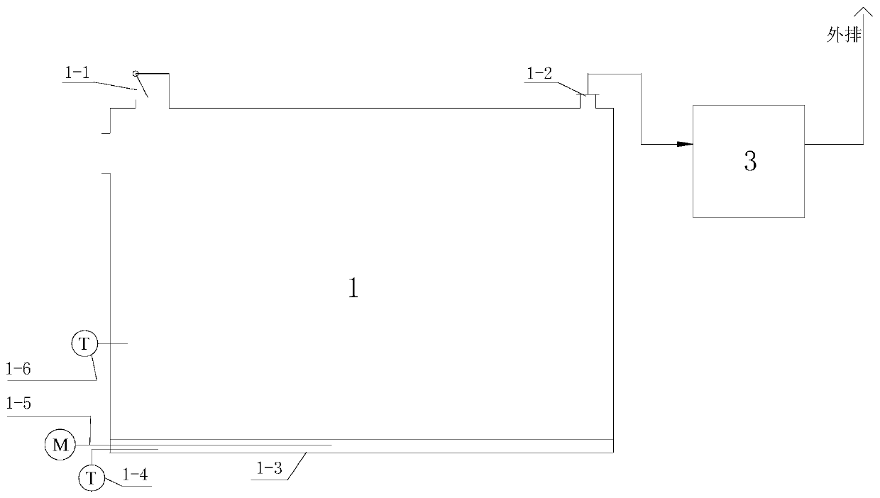
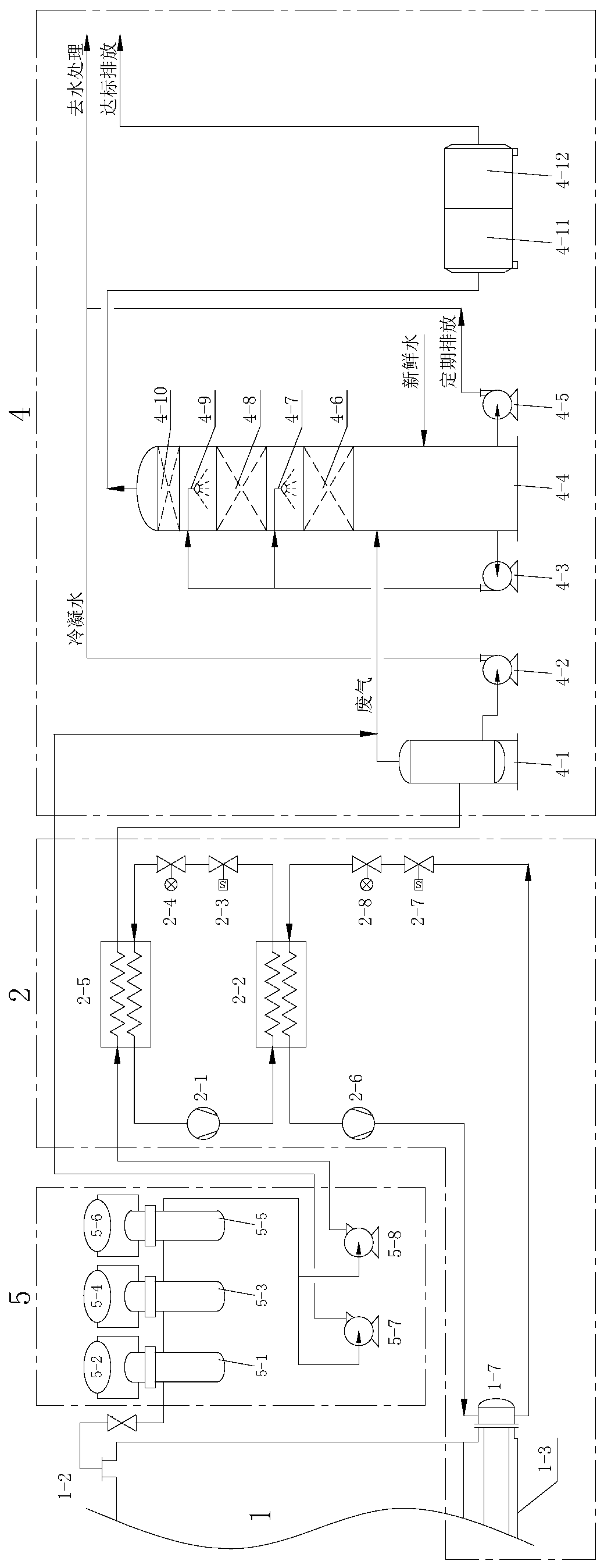
[0033] Such as figure 2 , image 3 As shown, it is an exhaust gas treatment device used in a food waste biochemical treatment equipment in Example 1 of the present invention, including a dust removal unit 5, a waste heat recovery unit 2 and a deodorization unit 4, a dust removal unit 5, a waste heat recovery unit 2 and a deodorization unit. The odor unit 4 is connected in turn through the gas delivery pipeline. The waste gas generated by the fermentation chamber 1 is first introduced into the dust removal unit 5 to filter impurities, then into the waste heat recovery unit 2 to recover waste heat, and then into the deodorization unit 4 to remove odor, and then discharged to the outside.

[0034] The exhaust gas treatment device in this embodiment adopts the process of "dust removal + waste heat recovery + deodorization" to treat the waste gas of the kitchen waste biochemical equipment, which can meet the requirements of emission standards, and at the same time, the waste heat ...

Embodiment 2

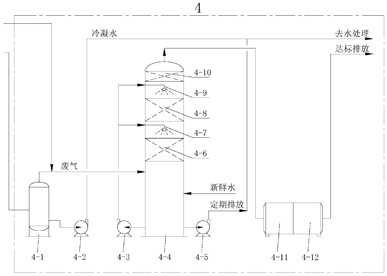
[0081] Such as Figure 4 As shown, it is the exhaust gas treatment device used in a kind of food waste biochemical treatment equipment in Example 2 of the present invention, and the difference from Example 1 is:

[0082] The secondary heat recovery unit of the waste heat recovery unit 2 also includes an economizer 2-11, a three-stage switch valve 2-9, and a three-stage expansion valve 2-10; the output port of the heater 1-7 of the fermentation chamber 1 is connected to two cooling refrigerant return path, the first refrigerant return path passes through the economizer 2-11, the secondary on-off valve 2-7, the secondary expansion valve 2-8, and the evaporative condenser 2-2 to return to the secondary compressor 2-6, The second refrigerant return path returns to the secondary compressor 2-6 through the three-stage on-off valve 2-9, the three-stage expansion valve 2-10, and the economizer 2-11.

[0083] The second refrigerant reflux path constitutes an air supplementary enthalpy...


PUM


Abstract

The invention relates to a waste gas treatment device used in kitchen waste biochemical treatment equipment. The device comprises a dust removal unit, a waste heat recovery unit and a deodorization unit, wherein the dust removal unit, the waste heat recovery unit and the deodorization unit are sequentially connected through a gas conveying pipeline, waste gas generated by a fermentation bin is firstly guided into the dust removal unit to filter impurities, then is guided into the waste heat recovery unit to recover waste heat, then is guided into the deodorization unit to remove odor, and thenis discharged outwards. According to the technical scheme provided by the invention, the waste gas of the kitchen waste biochemical equipment is treated by adopting a process of dust removal, waste heat recovery and deodorization, impurities and odor in the waste gas can be removed, and the waste heat of the waste gas is recovered, so that the effects of reducing environmental pollution, saving energy and reducing emission are achieved.

Description

technical field [0001] The invention belongs to the technical field of kitchen waste treatment, and in particular relates to a waste gas treatment device used in kitchen waste biochemical treatment equipment. Background technique [0002] With the acceleration of urbanization in our country, there are more and more urban kitchen wastes. Due to the characteristics of high water content, high organic matter content and high oil content, the centralized treatment is generally based on anaerobic fermentation treatment. Due to the consideration of the construction period, transportation cost and spillage during transportation, distributed on-site treatment has become a convenient treatment method for food waste treatment. [0003] Due to factors such as safety, distributed on-site treatment is generally carried out by aerobic fermentation using biochemical treatment equipment. The equipment has a fermentation bin and a stirring device in the bin. Due to factors such as the site, ...

Claims


Application Information

Patent Timeline
IPC IPC(8): B01D46/00B01D47/06B01D47/14B01D50/00B01D53/00B01D53/04B01D53/18B01D53/76B01D53/38F28D21/00
CPCB01D46/0012B01D50/00B01D47/06B01D47/14B01D53/18B01D53/185B01D53/007B01D53/04B01D53/76B01D53/38F28D21/0003B01D2259/804B01D2253/102B01D46/62Y02E50/30Y02P70/10
Inventor 陈子香常霄静李伟李锐白云峰裴少华初玮杨旭许鑫刘玉滨
Owner BEIJING CPCEP ENERGY CONSERVATION & ENVIRONMENTAL PROTECTION TECH CO LTD
Why Eureka
Try Eureka