Optical fiber passive online monitoring system and method for transformer winding vibration

A transformer winding and monitoring system technology, applied in the field of optical fiber passive online monitoring system, to achieve the effect of improving classification performance, avoiding weak adaptability and strong learning ability

Active Publication Date: 2020-07-24
南京艾森斯智能科技有限公司
View PDF11 Cites 10 Cited by
  • Summary
  • Abstract
  • Description
  • Claims
  • Application Information

AI Technical Summary

Problems solved by technology

At present, there are online monitoring methods for winding deformation and temperature based on the mechanism of Brillouin scattering (B-OTDR) and Raman scattering (R-OTDR) in optical fibers, but this type of technology only focuses on quasi-static variables such as winding deformation and nearby temperature. Direct measurement. At present, there is no precedent for dynamic direct measurement and online monitoring of the vibration state of windings and iron cores using fully distributed optical fiber vibration sensing technology in the transformer vibration online monitoring method.

Method used


Image

  • Optical fiber passive online monitoring system and method for transformer winding vibration
  • Optical fiber passive online monitoring system and method for transformer winding vibration
  • Optical fiber passive online monitoring system and method for transformer winding vibration

Examples


Embodiment 1

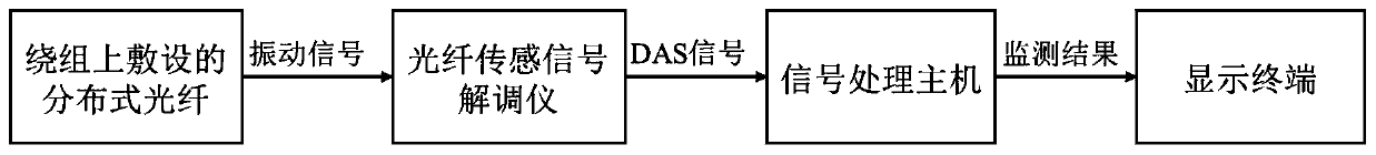
[0048] A device structure diagram of an optical fiber passive on-line monitoring system for transformer winding vibration figure 1 Shown:

[0049] Including: distributed optical fiber laid on the winding, optical fiber sensor signal demodulator, signal processing host, and display terminal.

[0050] The working process of the whole system is as follows: the highly narrow coherent laser pulse modulated by the acousto-optic modulator is amplified by the erbium-doped fiber amplifier, and enters the distributed optical fiber laid on the winding through the circulator. The scattered light will be modulated by the vibration of the transformer winding and carry vibration information. After the scattered light is filtered, it enters the interferometer for phase demodulation, and is converted into a digital signal by a photodetector and an analog-to-digital converter and sent to the signal processing host for subsequent processing. Analysis and data processing can identify the working...

Embodiment 1

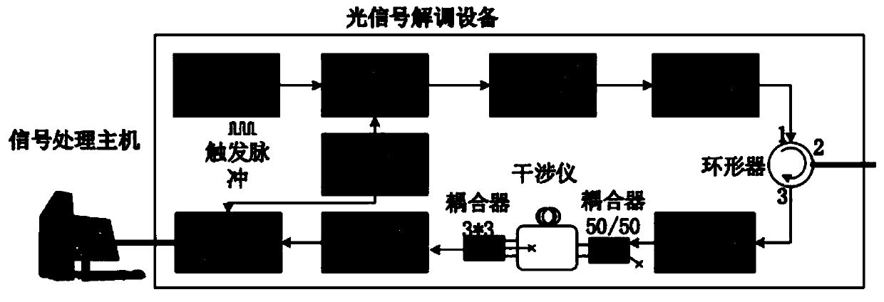
[0052] The optical fiber sensing signal demodulator in the first embodiment is the core module of the system, and its internal structure is as follows: figure 2 As shown, it is mainly composed of a narrow linewidth laser, an acousto-optic modulator, an erbium-doped fiber amplifier, an isolator, a circulator, a waveform generation card, an interferometer, a coupler, a filter, a photodetector, and an analog-to-digital converter. Its working principle is as follows: the system uses phase-sensitive optical time-domain reflectometry technology combined with unbalanced Mach-Zehnder linear phase demodulation method to linearly demodulate the phase change caused by winding vibration. Its internal components mainly include optical devices and electrical devices. kind. A continuous coherent optical signal is generated by an ultra-narrow linewidth laser, which is modulated into an optical pulse signal by an acousto-optic or electro-optic modulator. The optical pulse signal is amplified ...

Embodiment 3

[0058] On the basis of Embodiment 1 and Embodiment 2, this embodiment provides an effective laying method of distributed optical fibers on the winding. This laying method combines the mechanical structure characteristics of the internal winding and iron core of the transformer oil tank, especially the internal winding of the oil tank. The shape characteristics of the surface, using the flexibility and passive characteristics of the optical fiber, external winding and installation along the winding coil winding method before the transformer is energized.

[0059] The typical winding surface optical cable laying method and the whole monitoring system architecture are as follows: Figure 4 Said:

[0060] On the surface of the transformer winding, the optical cable is laid in a helical form. The diameter of the optical cable is determined by the diameter of the winding coil. Generally, the optical cable is about 2-3m long, so the optical pulse of the phase demodulator of the syste...


PUM


Abstract

The invention discloses an optical fiber passive online monitoring system and method for transformer winding vibration, and relates to the technical field of power system safety monitoring. A fully distributed optical fiber vibration sensing technology is adopted to perform dynamic direct measurement and online monitoring on the vibration states of an internal winding and an iron core of an oil tank of a transformer. By utilizing the passiveness and flexibility of an optical fiber, the system is mounted inside the high temperature oil tank of the transformer, and laid by winding along the winding; and in addition, in a way of deep learning feature and traditional artificial feature synchronous extraction and fusion, distinguishable features of a spatiotemporal vibration signal of the transformer winding under different failure modes are mined, and are classified and identified by adopting a variety of classifiers, the performance of the classifiers is evaluated, and finally the classifier with the best performance is selected for event classification to realize online monitoring and diagnosis for the winding. The method can achieve highly reliable and highly stable fault type identification, and can effectively avoid other inaccuracy of distance measurement outside the oil tank.

Description

technical field [0001] The invention relates to the technical field of power system safety monitoring, and more particularly relates to an optical fiber passive on-line monitoring system and method for winding vibration inside a transformer oil tank. Background technique [0002] Transformer is an important power transmission and transformation equipment in the power grid, which is expensive, and its stable operation status is of great significance to the safety and reliability of the power grid. However, due to the influence of the transformer's own structure and working environment and other factors, iron core and winding faults account for more than 90% of the accidents. These faults pose a serious threat to the safe operation of the power grid and cause huge economic losses. Therefore, on-line monitoring of transformers, early detection and elimination of potential failures before failures, has become an important method to ensure the reliability of power supply. [000...

Claims


Application Information

Patent Timeline
Patent Type & Authority Applications(China)
IPC IPC(8): G01H9/00G06K9/62G06N3/00G06N5/00G06N3/04G06N3/08
CPCG01H9/004G06N3/006G06N3/08G06N5/01G06N3/045G06F18/2411
Inventor 吴慧娟王宇丰王超群粟永阳袁平恒
Owner 南京艾森斯智能科技有限公司
Why Eureka
Try Eureka