
Annular microwave plasma resonant cavity

A microwave plasma and resonant cavity technology, which is applied in the direction of plasma, ion source/gun, particle separation tube, etc., can solve the problems of microwave energy reduction, reflection power increase, microwave matching component damage, etc., to reduce dimensional deformation, reduce Effects of microwave leakage and increased coupling ratio

Active Publication Date: 2020-08-14
FENGHUO COMM SCI & TECH CO LTD +1
View PDF7 Cites 0 Cited by
  • Summary
  • Abstract
  • Description
  • Claims
  • Application Information

AI Technical Summary

Problems solved by technology

[0004] Coaxial microwave plasma resonators are not suitable for manufacturing large-diameter optical fiber preforms due to structural limitations
Moreover, when high-power microwaves are input, the cavity and the coaxial waveguide are prone to heat, which may cause the resonant cavity or the coaxial waveguide to burn out.
[0005] The cylindrical microwave plasma resonator has the problem that the load is difficult to match, that is, the load reflection coefficient S cannot be guaranteed. 11 small enough
During the PCVD deposition process, vitrified doped SiO2 is deposited on the inner wall of the quartz tube reaction tube in a molten glass state, the thickness of the tube wall gradually increases, the inner diameter of the reaction tube is constantly decreasing, and the plasma density and morphology change, resulting in The load of the resonant cavity changes, and the load reflection coefficient S 11 will increase accordingly, so there is a possibility that the load cannot match
In addition, the load reflection coefficient S 11 Increase means that the reflected power increases, the microwave energy absorbed by the load decreases, and the energy utilization efficiency of the entire microwave system also decreases. In severe cases, the workload of the microwave matching component will increase or the microwave matching component will be damaged.

Method used


Image

  • Annular microwave plasma resonant cavity
  • Annular microwave plasma resonant cavity
  • Annular microwave plasma resonant cavity

Examples


Embodiment Construction

[0030] In order to make the purposes, technical solutions and advantages of the embodiments of the present application clearer, the technical solutions in the embodiments of the present application will be clearly and completely described below in conjunction with the drawings in the embodiments of the present application. Obviously, the described embodiments It is a part of the embodiments of this application, but not all of them. Based on the embodiments in the present application, all other embodiments obtained by persons of ordinary skill in the art without making creative efforts belong to the protection scope of the present application.

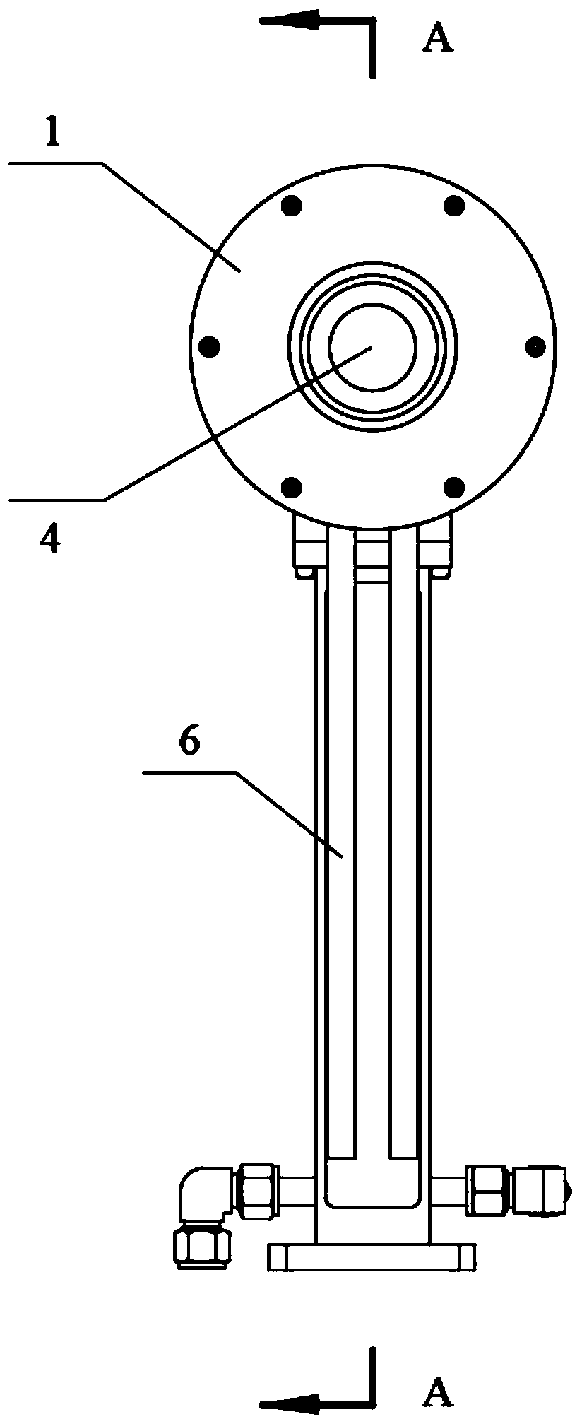
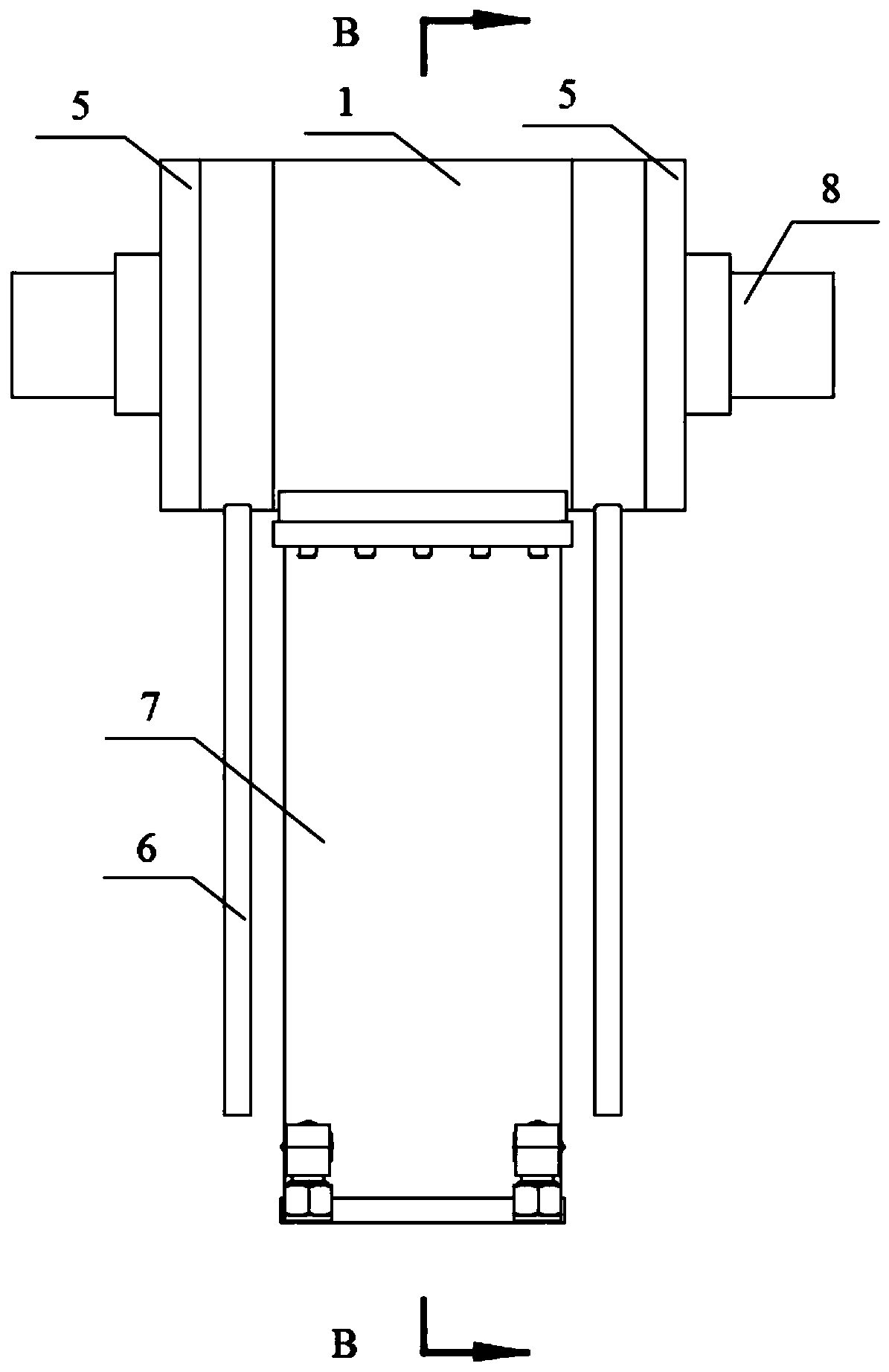
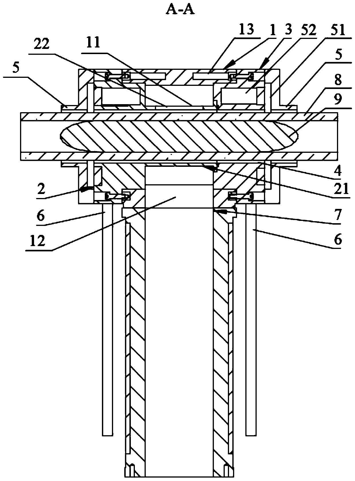
[0031] see Figure 1 to Figure 4 As shown, the embodiment of the present invention provides a ring-shaped microwave plasma resonant cavity, which includes a resonant cavity shell 1 , a first cut-off waveguide 2 and a second cut-off waveguide 3 .

[0032] Wherein, the resonant cavity shell 1 is provided with a cavity 11 therein. In thi...


PUM


Abstract

The invention discloses an annular microwave plasma resonant cavity, and relates to the field of microwave plasma resonant cavities. The annular microwave plasma resonant cavity comprises a resonant cavity shell with a cavity body inside, a first cut-off waveguide which is fixed at one end of the resonant cavity shell and comprises a cylinder body accommodated in the cavity, and a second cut-off waveguide fixed at the other end of the resonant cavity shell, wherein the cylinder body and the resonant cavity shell form an annular cavity, a plurality of slits are formed in the cylinder body, at least part of the second cut-off waveguide extends into the cavity to be connected with the cylinder body, and the second cut-off waveguide is communicated with the cylinder body to form a mounting hole for accommodating a quartz reaction tube. According to the annular microwave plasma resonant cavity, the load reflection coefficient S11 can be kept at a low level, and the coupling rate of microwave energy can be improved, so that high-density plasma is obtained.

Description

technical field [0001] The invention relates to a plasma resonant cavity, in particular to an annular microwave plasma resonant cavity. Background technique [0002] The PCVD (Microwave Activated Plasma Chemical Vapor Deposition, microwave activated plasma chemical vapor deposition) process is one of the main processes for preparing the optical fiber preform core rod. Because microwave plasma has the advantages of high energy, strong activity, high excited plasma density, stable operation, and no electrode pollution, it is very suitable for the deposition of optical fiber preforms. Under low pressure, due to the action of high-frequency microwaves, the raw material gas (mainly SiCl4, GeCl4, POCl3, O2 and C2F6, etc.) entering the quartz reaction tube is partially ionized into an activated plasma state, and these active ions can quickly The reaction occurs, and the reaction product is deposited on the inner surface of the tube wall in a glassy state. Due to the rapid movemen...

Claims


Application Information

Patent Timeline
Patent Type & Authority Applications(China)
IPC IPC(8): H05H1/46H01J49/10
CPCH05H1/46H01J49/105H05H1/461Y02E30/10
Inventor 蔡冰峰刘志坚黄文俊曾建军岳静
Owner FENGHUO COMM SCI & TECH CO LTD
Features
  • Generate Ideas
  • Intellectual Property
  • Life Sciences
  • Materials
  • Tech Scout
  • Unparalleled Data Quality
  • Higher Quality Content
  • 60% Fewer Hallucinations
Learn More