
Gas-solid reducing vertical furnace and sponge iron production method

A technology of sponge iron and shaft furnace, which is applied in the direction of shaft furnace, furnace, furnace type, etc., can solve the problems of high thermal performance requirements of furnace pellets, insufficient comprehensive heat utilization efficiency, increased material running resistance, etc., and achieve shortened reduction time, simplification of gas production and reforming process, and improvement of reduction efficiency

Active Publication Date: 2020-08-25
WUHAN COSRED SCI & TECH LTD
View PDF10 Cites 5 Cited by
  • Summary
  • Abstract
  • Description
  • Claims
  • Application Information

AI Technical Summary

Problems solved by technology

For example, as proposed by patent CN110106303A, multiple layers and several heat-resistant steel pipes are set in the shaft furnace, and high-temperature reducing gas is injected to achieve the effect of gas reduction at the same time as coal-based reduction. The advantage is that it fully solves the problem of high-temperature reducing gas entering the furnace. The problem is that there are many reducing gas pipes in the furnace, which increases the running resistance of the material from top to bottom, the heat-resistant pipe wears a lot and the material cost is high, and the size of a single set of devices is limited, making it difficult to enlarge; such as the patent CN110438278A and CN110453027A respectively propose that from the upper part of the shaft furnace and the middle part of the shaft furnace, the heat-carrying gas is sprayed into the shaft furnace in a countercurrent or downstream manner to realize the dry distillation of high-volatile coal and generate pyrolysis gas. The iron-containing ore is put into the furnace for reduction, and the final products are reduced iron and semi-coke. The advantage is that it uses the heat transfer characteristics of the gas-based shaft furnace for reference, and uses the pyrolysis gas of high-volatility solid carbon material as the reducing gas to realize gas-solid The organic combination of reduction makes the device easy to enlarge; the disadvantage is that due to the short air flow stroke in a single shaft furnace, the temperature of the furnace top gas is high, the comprehensive heat utilization efficiency is insufficient, and when the heat carrier gas is fed from the upper part of the shaft furnace , the requirements for the rapid heating performance of the pellets into the furnace are relatively high

Method used


Image

  • Gas-solid reducing vertical furnace and sponge iron production method
  • Gas-solid reducing vertical furnace and sponge iron production method
  • Gas-solid reducing vertical furnace and sponge iron production method

Examples


Embodiment 1

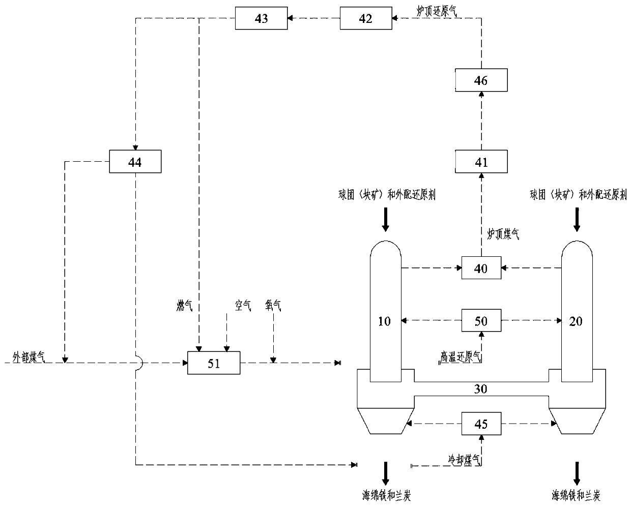
[0055] (1) Use coke oven gas as external gas, and crushed coke as external reducing agent. Mix according to the mass ratio of pellets (15~35mm) and crushed coke (5~15mm) of 1:0.2 from the first shaft furnace Continuously add to the empty section of the second shaft furnace;

[0056] (2) The coke oven gas is heated to 600~750℃ by the heating furnace, after adding some oxygen, it is heated to 900~950℃, and sent into the first shaft furnace through the high-temperature reducing gas reversing valve group; pellets and crushed coke The mixture is parallel to the high-temperature reducing gas from top to bottom. During the process, the pellets are reduced to produce H 2 O and CO 2 Further oxygen-abstraction reaction with C in the crushed coke to generate CO and H 2 Then re-participate in the reduction reaction of pellets;

[0057] (3) The high-temperature reducing gas descends to the equal pressure section, enters the second shaft furnace from the first gas ring channel and the intermedia...

Embodiment 2

[0062] (1) Use upgraded semi-coke oven gas as external gas, semi-coke as external reducing agent, and mix according to the mass ratio of pellets (15~35mm) to semi-coke (5~25mm) of 1:0.2. Continuously add from the empty section of the first shaft furnace and the second shaft furnace;

[0063] (2) The upgraded semi-coke oven gas is heated by a heating furnace to 600-750°C, mixed with part of oxygen, heated to 900-950°C, and sent into the first shaft furnace through a high-temperature reducing gas reversing valve group; The mixture of pellets and semi-coke is parallel to the high-temperature reducing gas from top to bottom. During the process, the pellets are reduced to produce H 2 O and CO 2 Further oxygen abstraction reaction with C in the semi-coke to generate CO and H 2 Then re-participate in the reduction reaction of pellets;

[0064] (3) The high-temperature reducing gas descends to the equal pressure section, enters the second shaft furnace from the first gas ring channel and t...

Embodiment 3

[0069] (1) Use ordinary semi-coke oven gas as the external gas and lignite as the external reducing agent, and mix according to the mass ratio of pellets (15~35mm) and lignite (15~50mm) into the furnace of 1:0.35. Continuous addition of the empty material section of the furnace and the second shaft furnace;

[0070] (2) The semi-coke oven gas is heated to 600~750℃ by the heating furnace, after adding some oxygen, it is heated to 950~1050℃, and sent into the first shaft furnace through the high-temperature reducing gas reversing valve group; pellets and lignite The mixture is parallel to the high-temperature reducing gas from top to bottom. During the process, the pellets are reduced to produce H 2 O and CO 2 Further oxygen-abstraction reaction with C in lignite produces CO and H 2 Then re-participate in the reduction reaction of pellets;

[0071] (3) The high-temperature reducing gas descends to the equal pressure section, enters the second shaft furnace from the first gas ring cha...


PUM


Abstract

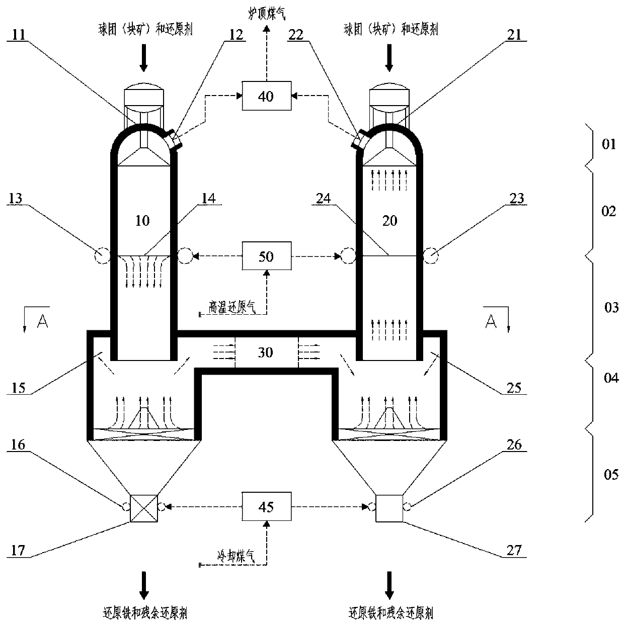
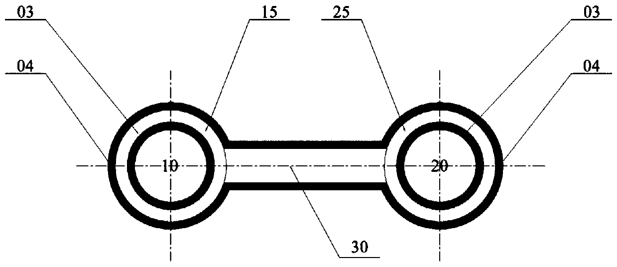
The invention provides a gas-solid reducing vertical furnace and a sponge iron production method. Two vertical furnaces are adopted in the gas-solid reducing vertical furnace, and furnace roof gas, high-temperature reducing gas, intermediate gas and cooling gas of the two vertical furnaces are connected. The sponge iron production method comprises the steps that after iron containing pellets or block ore and an externally-matched reducing agent are mixed, the mixture is continuously added into the two vertical furnaces, the high-temperature reducing gas enters the vertical furnaces under switching of a reversing valve set, parallel flow heating and adverse flow heat storage are conducted in the first vertical furnace and the second vertical furnace at the same time in the airflow direction, the destructive distillation and reducing reaction is generated, and sponge iron, semi-coke and furnace roof gas are generated; and after the furnace roof gas is purified, the furnace roof gas serves as heating furnace fuel, cyclic reducing gas and cyclic cooling gas to be used; through gas heat transfer, the heat efficiency is improved, and the reducing progress is better accelerated; due to the communicating double-vertical-furnace structure, the gas stroke is increased, the temperature of the furnace roof gas is reduced, and the gas utilization rate is increased; and due to gas flow online switchover, double-vertical-furnace temperature field synchronism and uniformity are achieved, and the problem about synchronous running is solved.

Description

Technical field [0001] The invention belongs to the technical field of direct reduction, and specifically relates to a gas-solid reduction shaft furnace and a method for producing sponge iron. Background technique [0002] In order to get rid of the fetters of the shortage of coking coal resources on the development of the metallurgical industry, to meet the requirements of environmental protection, and to further reduce the energy consumption of the ironmaking process, non-blast furnace ironmaking technology with direct reduction as one of the main development directions has increasingly become the development and Focus of attention. [0003] As a new ironmaking technology, direct reduction technology has two types: gas-based direct reduction and coal-based direct reduction. The gas-based direct reduction uses the reducing gas composed of H2 and CO as the reducing agent, and the iron oxide in the iron ore is reduced to sponge iron at a solid temperature in a shaft furnace or a ta...

Claims


Application Information

Patent Timeline
Patent Type & Authority Applications(China)
IPC IPC(8): C21B13/02
CPCC21B13/029C21B13/0073C21B2100/66C21B2100/44Y02P10/122
Inventor 汪朋周强李森蓉李建涛唐恩付邦豪陈泉锋
Owner WUHAN COSRED SCI & TECH LTD
Learn More