Waste boiler gasification device and method for recovering waste heat of dry pulverized coal

A technology of gasification device and dry coal powder, applied in the field of gasifier, can solve the problems of complex process flow, increase heat recovery rate, substandard cooling, etc., so as to solve complex process flow, reduce water consumption, and increase heat recovery rate effect

Pending Publication Date: 2020-09-11
宁夏神耀科技有限责任公司
View PDF0 Cites 4 Cited by
  • Summary
  • Abstract
  • Description
  • Claims
  • Application Information

AI Technical Summary

Problems solved by technology

[0004] This application provides a waste boiler gasification device and method for recovering waste heat of dry coal powder. It adopts the design of radiant waste boiler plus cooling nozzle combined with convection waste boiler. The radiant waste boiler is designed as a two-stage water wall structure to increase the coal gasification process. The heat recovery rate in the middle solves the problems of complex process flow of the existing waste boiler gasification furnace, difficult maintenance of the waste boiler system, substandard cooling, and large investment; solves the problem that the existing gasification process cannot be designed for convection after radiating the waste boiler The problem of waste boilers, while recovering the sensible heat of high-temperature syngas to the greatest extent, can greatly reduce water consumption

Method used


Image

  • Waste boiler gasification device and method for recovering waste heat of dry pulverized coal
  • Waste boiler gasification device and method for recovering waste heat of dry pulverized coal

Examples


Embodiment Construction

[0028] The embodiments will be described in detail hereinafter, examples of which are illustrated in the accompanying drawings. When the following description refers to the accompanying drawings, the same numerals in different drawings refer to the same or similar elements unless otherwise indicated. The implementations described in the following examples do not represent all implementations consistent with this application. These are merely examples of systems and methods consistent with aspects of the present application as recited in the claims.

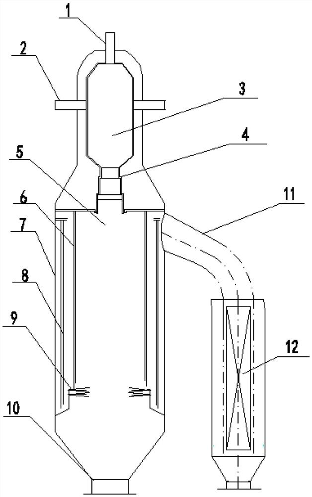
[0029] see figure 1 , is a schematic structural diagram of a waste boiler gasification device for recovering waste heat from dry coal powder.

[0030] A waste boiler gasification device for recovering waste heat of dry coal powder provided by the present application includes a shell 7, and inside the shell 7, there are a combustion chamber 3 and a radiant waste boiler 5 that communicate with each other from top to bottom. The b...


PUM


Abstract

A waste boiler gasification device for recovering waste heat of dry pulverized coal comprises a shell, wherein a combustion chamber and a radiation waste boiler which are communicated with each otherare arranged in the shell from top to bottom, an overhead combustor is installed at the top end of the combustion chamber, 2N side combustors are symmetrically installed on the two sides of the combustion chamber, and a slag opening is formed in the bottom of the combustion chamber; the radiation waste boiler is communicated with the lower end of the slag hole, a first-stage water cooling wall anda second-stage water cooling wall are separately arranged in the radiation waste boiler from inside to outside in parallel at intervals, wherein a cooling spray head is mounted below the first-stagewater cooling wall, and slag discharge holes are formed in the radiation waste boiler and the bottom of the shell; a synthesis gas outlet is formed in the side face of the upper portion of the radiation waste boiler and connected with a gas conveying guide pipe, and the other end of the gas conveying guide pipe communicates with the convection waste boiler. Based on the design of the radiation waste heat boiler and the convection waste heat boiler, the radiation waste heat boiler is formed by combining the two layers of water cooling walls with the rising secondary channel and the convection waste heat boiler, sensible heat of high-temperature synthesis gas can be recycled to the maximum extent, the heat utilization rate is high, and the process is simple.

Description

technical field [0001] The present application relates to the technical field of gasification furnaces, in particular to a waste boiler gasification device and method for recovering waste heat of dry coal powder. Background technique [0002] The efficient and clean utilization of coal is an inevitable strategic choice for sustainable economic and social development, and an important basis for ensuring stable and reliable energy supply and sustainable development. In the clean and efficient utilization of coal, coal gasification technology occupies a core position. Dry coal powder pressurized entrained bed gasification technology has become the mainstream technology in industrial operation due to its advantages such as wide adaptability of coal types, high gasification efficiency, and superior environmental protection performance. [0003] The dry coal gasification technology operating in the coal gasification market at this stage, common aerospace furnaces and Dongfang furn...

Claims


Application Information

Patent Timeline
Patent Type & Authority Applications(China)
IPC IPC(8): C10J3/48C10J3/50C10J3/72C10J3/74C10J3/86
CPCC10J3/48C10J3/50C10J3/725C10J3/74C10J3/86C10J2300/1631Y02P20/10Y02P20/129
Inventor 张镓铄马丹丹夏支文蔡力宏匡建平张亚宁马钊杜常宗袁继禹白云波陈毅烈庄忠华刘旭军
Owner 宁夏神耀科技有限责任公司
Why Eureka
Try Eureka