
Wearable lower limb rehabilitation training system

A rehabilitation training and wearable technology, applied in passive exercise equipment, physiotherapy, equipment to help people walk, etc., can solve the problems of heavy equipment, increased power consumption, motor heating, etc., to reduce the cost of use, the overall weight Lighten and improve blood circulation

Pending Publication Date: 2020-09-25
河南省祥和康复产业技术研究院有限责任公司
View PDF0 Cites 0 Cited by
  • Summary
  • Abstract
  • Description
  • Claims
  • Application Information

AI Technical Summary

Problems solved by technology

This kind of training is carried out through the current wearable lower limb rehabilitation training system (also called lower limb exoskeleton robot). Driven by the controller, the overall system is equipped with a battery, and then under the control of the algorithm set in the controller or partly under the feedback of the sensor signal, the controller controls the joint movement through the controller to drive the patient to walk and assist the patient in rehabilitation. , this kind of rehabilitation training equipment needs to meet the following requirements: first, safety and stability, the user's balance ability and exercise adjustment ability are generally not good, safety and stability are the most basic and important requirements for this type of equipment; second It can be worn by different patients. Due to the large differences in the height, fat and thinness, gender, and proportion of various body parts of patients, the cost of manufacturing and using each patient is too high, so it is required that the equipment can be standardized. The third is the battery life of the device. Since the device not only drives the device itself, but also drives the legs of the human body to move, it needs a certain amount of power, and the configured battery If the capacity is too large, the device will be heavy, and the device will be connected to the patient through the waistline. The overweight device will put too much pressure on the patient's back, and the battery will heat up during use, which will bring a lot of discomfort to the patient; the fourth is comfort. , due to the psychological problems caused by the patient's own disease, if some parts or components bring bad feelings during training, it will make the patient feel irritable and affect the effect of rehabilitation training
Chinese Patent No. 2018108898016 discloses a rehabilitation lower extremity exoskeleton, claiming that it can realize the function of helping patients walk, but there are many problems in it, which basically cannot meet any of the above requirements. One is the structural problem of the hip joint. The mechanism is a very important mechanism in the equipment to realize the movement of the thigh, but the weight of the thigh is relatively heavy, and the drive itself requires a large power. In this patent, the ball screw is used to drive the connecting rod to drive the hip joint, and there are the following problems: First, The driving motor of the ball screw is arranged "head down". The ball screw is located at the waist above the hip joint, but the distance between the waist and the hip joint is very short, so the moment arm is very short when the linkage mechanism is used to drive the hip joint. This requires the screw to be equipped with a motor with a higher power, and this method of driving the hip joint is a "lever type" drive. Due to the heavy weight of the legs, the whole leg is a resistance arm, which is conceivable. The power of the motor will be very large, and its driving force arm will gradually become shorter during the rotation of the hip joint, and the required driving force will also increase. Using a motor with a higher power will cause a series of problems, such as: a: The power of the motor Both increase the power consumption of the equipment and shorten the continuous operation time of the equipment under the condition of a certain battery capacity; b: the overall weight of the equipment increases, and the motor is installed at a high position, which leads to a high overall center of gravity of the equipment , unstable; c: The motor heats up seriously during operation, which will make the patient feel uncomfortable in the waist; the second is that the ball screw is directly connected to the motor or connected through a reducer, and the screw is directly connected to the motor or decelerated On the machine, the connections between the driving device and the lead screw and between the lead screw and the connecting rod are all hard connections, which requires high precision during the installation and manufacture of the equipment. If the error is slightly large or some parts in use If it is loose, it will be stuck, and the joints of the equipment manufactured by this hard connection drive are very stiff during operation, the vibration is large, the adaptability to the human joints is poor, and the comfort is poor
The third is that the hip joint structure of this patent has a swinging block that swings outwards and retracts. There is no rigid restraint in this position, and this position will follow-up during use, because this type of patients generally have poor self-control ability, which will cause As a result, the patient walks unstable during the training process, and the gait cannot be completed according to the therapist's design; fourth, the device uses straps to fix the thigh and calf, which is too tight for the patient's legs, and the comfort is extremely poor; fifth, The device cannot be effectively adjusted for patients with large differences in height, weight, gender, and body parts. Therefore, the above-mentioned problems of the device greatly reduce the possibility of its use in practice. Cannot meet the basic requirements of wearable lower body training system

Method used


Image

  • Wearable lower limb rehabilitation training system
  • Wearable lower limb rehabilitation training system
  • Wearable lower limb rehabilitation training system

Examples


Embodiment Construction

[0029] In order to more fully explain the implementation of the present invention, implementation examples of the present invention are provided. These implementation examples are only illustrations of the present invention, and do not limit the scope of the present invention.

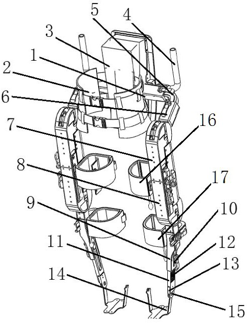
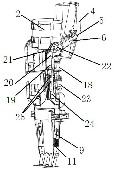
[0030] A further detailed explanation of the present invention is given in conjunction with the accompanying drawings. In the accompanying drawings, each mark is: 1: beam; 2: waist circumference; 3: battery box assembly; 4: armrest; 5: L-shaped piece; 6: connecting sleeve; 7: thigh Shell; 8: knee joint assembly shell: 9: fixed calf plate; 10 long hole; 11: movable calf plate; 12: toothed surface; 13: U-shaped mouth; 14: shoe holder; 15: ankle joint shaft; 16 : Thigh restraint airbag cover; 17: Calf restraint airbag cover; 18: Driving motor of hip joint screw; 19: Hip joint screw; 20: Hip joint drive sleeve; 21: Hip joint connecting rod; 22: Hip joint crank; 23: drive motor of knee screw; 24: orifice p...


PUM


Abstract

The invention discloses a wearable lower limb rehabilitation training system. The training system includes a crossbeam, a girdle fixedly connected to the crossbeam, a battery box assembly, a controller, a left lower limb system and a right lower limb system; the left lower limb system includes a thigh frame; the thigh frame includes a thigh installation plate; a hip joint lead screw is connected to the thigh installation plate; a nut of the lead screw is fixedly connected to a hip joint sliding block; one end of a hip joint connecting rod is in hinged joint with the hip joint sliding bloc, andthe other end of the hip joint connecting rod is in hinged joint with a hip joint crank; the left lower limb system also includes a knee joint assembly located under the thigh frame; the lower end ofthe knee joint assembly is fixedly connected to a calf mechanism with adjustable length; the lower part of the calf mechanism with adjustable length is rotatably connected to a ankle joint, and a shoes holder is connected under the ankle joint; and the thigh frame and a calf frame are fixedly connected to straining gasbag coats. The training system can be used for helping patients with differenttypes of lower limb dysfunction to walk.

Description

technical field [0001] The invention relates to rehabilitation training equipment, in particular to wearable lower limb rehabilitation training equipment, and belongs to the technical field of rehabilitation training equipment. Background technique [0002] At present, more and more patients are suffering from hemiplegia, paraplegia, or severe damage to the joints of the lower limbs due to various reasons such as stroke, joint-shaped diseases, and traffic accidents. This function can cause irreversible damage. Assisted walking training for such patients can not only help patients recover their walking ability, but also avoid long-term sedentary pressure sores, which can improve the heart function, muscle strength and balance ability of patients. benefit. This kind of training is carried out through the current wearable lower limb rehabilitation training system (also called lower limb exoskeleton robot). Driven by the controller, the overall system is equipped with a batter...

Claims


Application Information

Patent Timeline
Patent Type & Authority Applications(China)
IPC IPC(8): A61H3/00A61H1/02
CPCA61H3/00A61H1/0262A61H2003/007A61H2003/005A61H2201/165A61H2201/1207A61H2201/1418A61H2201/1436A61H2201/1659
Inventor 何永正王光旭张玉刚司世雄
Owner 河南省祥和康复产业技术研究院有限责任公司
Learn More